
Method for manufacturing a fluid-ejection device with improved resonance frequency and fluid-ejection velocity, and fluid-ejection device

a technology of fluid-ejection device and resonance frequency, which is applied in the direction of micro-structural device, coating, printing, etc., can solve the problems of large thickness of the device, high cost and high precision of the method, and the resonance frequency of the print head deterioration

Active Publication Date: 2019-07-18
STMICROELECTRONICS SRL
View PDF3 Cites 1 Cited by
  • Summary
  • Abstract
  • Description
  • Claims
  • Application Information

AI Technical Summary

Benefits of technology

The patent describes how two wafers can be combined by using tools during bonding. The wafers have a minimum thickness, but they need to be thicker to allow for handling. The patent explains how a fluid can be ejected through a channel from a contained chamber to a nozzle, and how this channel increases the thickness of the wafer to allow for easier handling. The technical effect of this invention is the ability to bond two wafers together using tools and a thicker fluid-contained chamber, thereby improving the manufacturing process.

Problems solved by technology

Known manufacturing methods envisage coupling via gluing or bonding of a large number of pre-machined parts; however, said method is costly and requires high precision, and the resulting device has a large thickness.
The present applicant has found that the presence of the above feeding channel may cause, in given operating conditions, a deterioration of the resonance frequency of the print head and may likewise affect the velocity of fluid ejection from the nozzle, thereby reducing it.

Method used


Image

  • Method for manufacturing a fluid-ejection device with improved resonance frequency and fluid-ejection velocity, and fluid-ejection device
  • Method for manufacturing a fluid-ejection device with improved resonance frequency and fluid-ejection velocity, and fluid-ejection device
  • Method for manufacturing a fluid-ejection device with improved resonance frequency and fluid-ejection velocity, and fluid-ejection device

Examples


Embodiment Construction

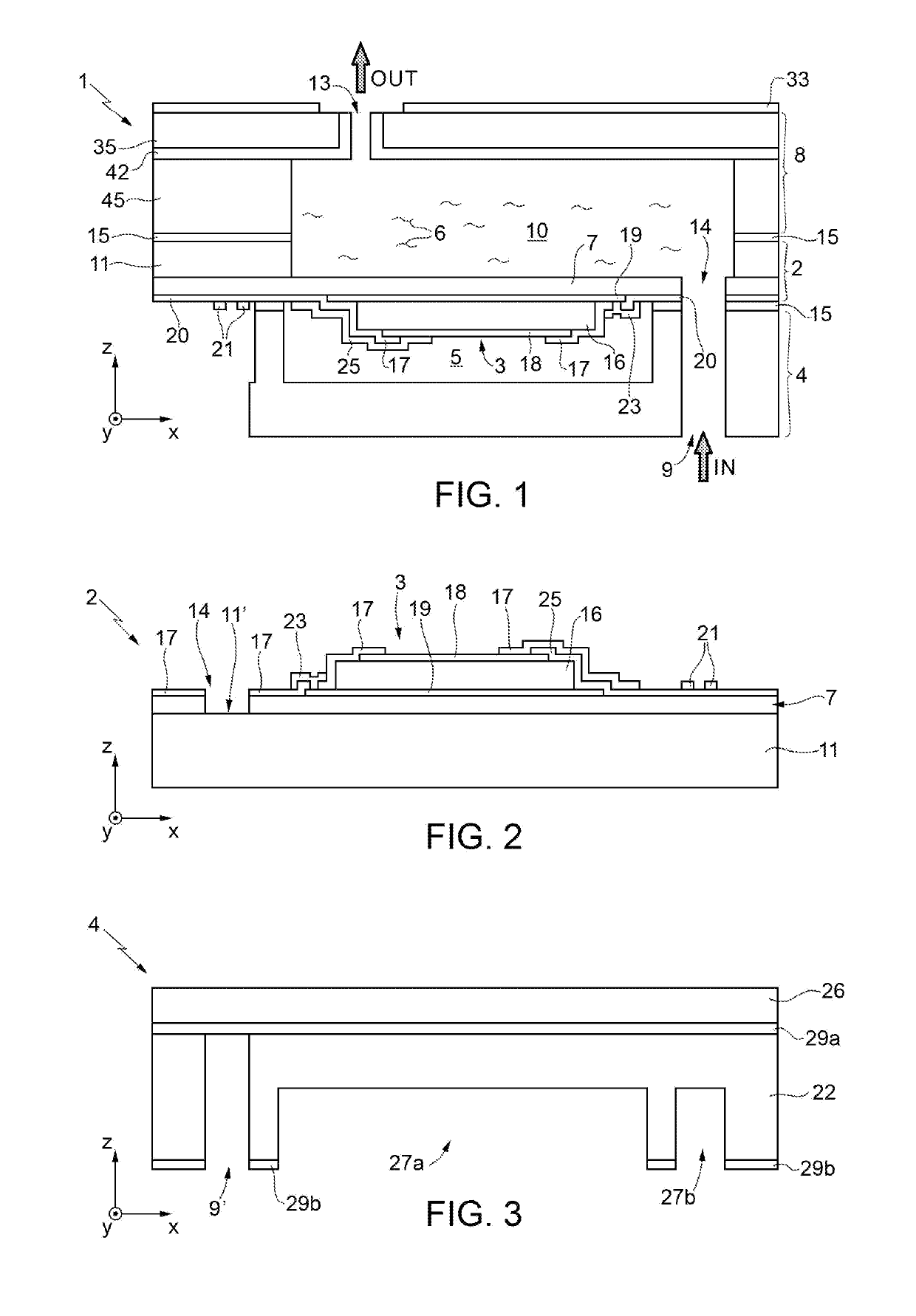
[0014]Fluid-ejection devices based upon piezoelectric technology may be manufactured by bonding or gluing together a plurality of wafers previously machined by micromachining technologies typically used for manufacturing MEMS (Micro-Electro-Mechanical Systems) devices. In particular, with reference to FIG. 1, a liquid-ejection device 1 is illustrated according to an aspect of the present disclosure. With reference to FIG. 1, the liquid-ejection device 1 comprises a first wafer 2, a second wafer 4, and a third wafer 8.

[0015]The first wafer includes a substrate 11 and at least one piezoelectric actuator 3, which is designed to be governed for generating a deflection of a membrane 7 coupled thereto. The membrane 7 extends partially suspended over at least one chamber 10 that defines a reservoir for containing fluid 6 to be expelled during use.

[0016]The second wafer 4 defines at least one containment chamber 5 of the piezoelectric actuator 3 configured to isolate, in use, the piezoelect...


PUM

PropertyMeasurementUnit
Fractionaaaaaaaaaa
Fractionaaaaaaaaaa
Thicknessaaaaaaaaaa

Abstract

A method for manufacturing a device for ejecting a fluid, comprising the steps of: forming, in a first semiconductor wafer that houses a nozzle of the ejection device, a first structural layer; removing selective portions of the first structural layer to form a first portion of a chamber for containing the fluid; removing, in a second semiconductor wafer that houses an actuator of the ejection device, selective portions of a second structural layer to form a second portion of the chamber; and coupling together the first and second semiconductor wafers so that the first portion directly faces the second portion, thus forming the chamber. The first portion defines a part of volume of the chamber that is larger than a respective part of volume of the chamber defined by the second portion.

Description

BACKGROUNDTechnical Field[0001]The present disclosure relates to a method for manufacturing a fluid-ejection device and to a fluid-ejection device.Description of the Related Art[0002]Known in the prior art are multiple types of fluid-ejection devices, in particular inkjet heads for printing applications. Similar heads, with appropriate modifications, may likewise be used for ejection of fluids other than ink, for example for applications in the biological or biomedical field, for local application of biological material (e.g., DNA) in the manufacture of sensors for biological analyses, for decoration of fabrics or ceramics, and in 3D-printing and additive-production applications.[0003]Known manufacturing methods envisage coupling via gluing or bonding of a large number of pre-machined parts; however, said method is costly and requires high precision, and the resulting device has a large thickness.[0004]To overcome the above drawbacks, U.S. Pat. Pub. No. 2014 / 0313264 discloses a meth...

Claims


Application Information

Patent Timeline
IPC IPC(8): B41J2/16B41J2/14B81C1/00
CPCB41J2/1626B41J2/1623B41J2/1632B41J2/14201B41J2/1607B81C1/00087B41J2/01B41J2/1606B41J2/161B41J2/1628B41J2/1629B41J2/1631B41J2/1642B41J2002/14241B41J2/14233B41J2002/14491
Inventor GIUSTI, DOMENICOFERRERA, MARCOPRELINI, CARLO LUIGICATTANEO, MAURONOMELLINI, ANDREA
Owner STMICROELECTRONICS SRL
Learn More