Boat Gate

a technology for boats and gates, applied in the field of boats, can solve the problems of compromising the protection of the barrier system, introducing its own set of potential issues and hazards, and allowing personnel to latch/unlock the barrier unit to pinch or smash fingers, etc., and achieve the effect of wide opening

Active Publication Date: 2019-07-11
OCEANETICS
View PDF0 Cites 2 Cited by
  • Summary
  • Abstract
  • Description
  • Claims
  • Application Information

AI Technical Summary

Benefits of technology

[0014]The boat gate system embodying the principles of the present invention fundamentally comprises a means of remotely latching and unlatching a PSB gate segment, combined with a means for moving the PSB gate segment to a desired position and back to a latched position, the means for moving the PSB segments being self-contained on the PSB segment and remotely operable, both as to direction and force/speed. In a preferred embodiment, one or more of the PSB segments in a new or existing PSB system will comprise the remote latching/unlatching and motive apparatus, thereby modifying that segment into a barrier latching unit (BLU).
[0015]In one embodiment, the BLU comprises a remote controlled latching mechanism and remote controlled thrusters; the thrusters are configured to move the PSB string laterally away from the other portion of the latching mechanism (that is, in an arcuate direction, swinging the PSB gate segment away from its latched position) as well as axially (in effect, pulling on it along its axis), so as to keep the catenary in the string such that the PSB modules...

Problems solved by technology

The process of manually latching and unlatching a PSB unit so that a gate can be opened and closed and of moving the PSB units to/from an open position introduces many safety hazards.
Since both the barrier/gate itself and the boat pulling the barrier unit/gate are in constant motion on the water, the possibility for personnel latching/unlatching the barrier unit to pinch or smash fingers, hands, wrists, arms, feet, ankles or legs is a very real and present danger in each latching/unlatching operation.
In addition, due to this safety issue, there are instances where barrier operators do not properly latch the gate; this causes the protection of the barrier system to be compromised.
Further, the PSB unit may be temporarily tethered to the boat to move it, introduci...

Method used


Image

  • Boat Gate
  • Boat Gate
  • Boat Gate

Examples


Embodiment Construction

)

[0025]While various boat gates can embody the principles of the present invention, with reference to the drawings some of the presently preferred embodiments can be described.

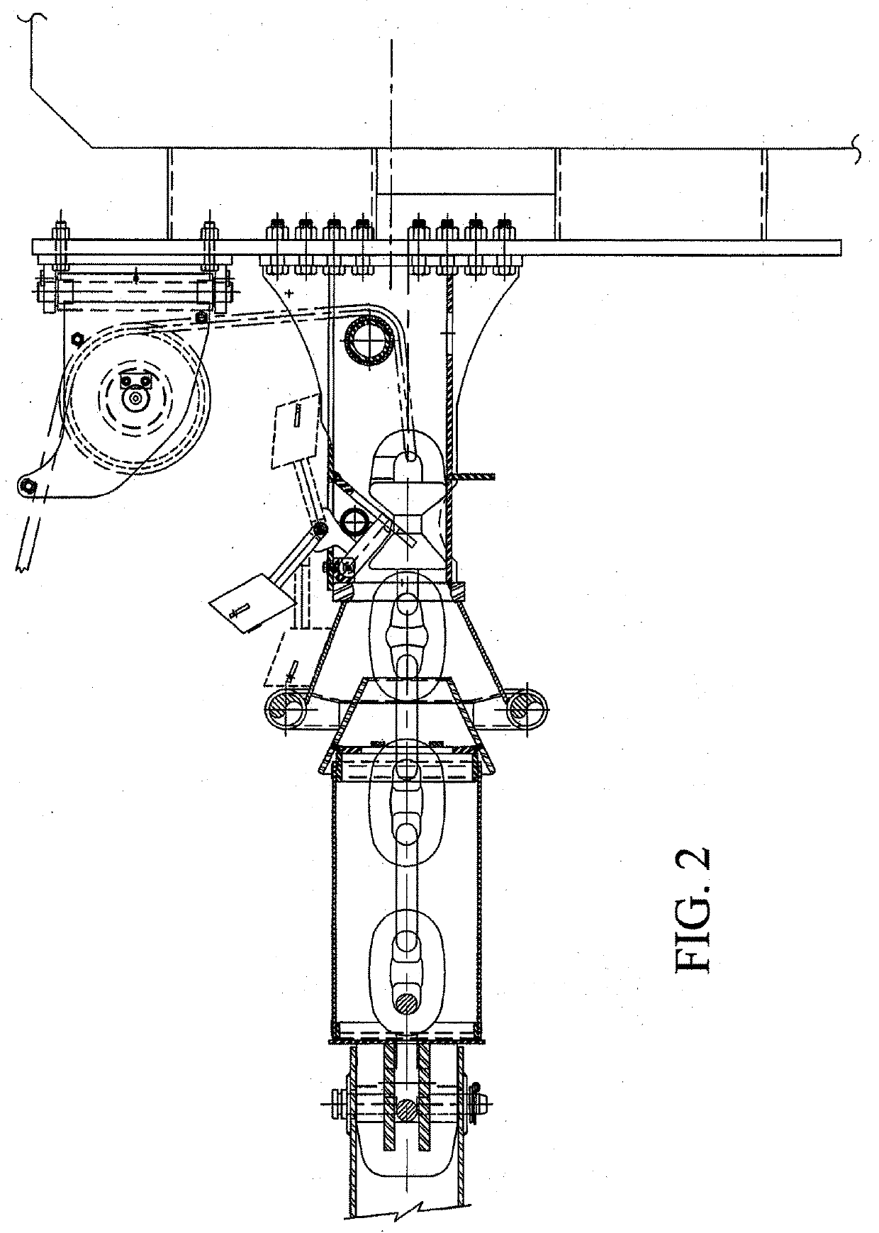
[0026]Referring to FIGS. 5 and 6, these figures show various elements which may be installed onto a PSB segment to form a BLU, in one embodiment of the present invention. A remote controlled latching mechanism comprises a latch 210, which may be a sliding throated element as shown or a similar structure, which engages and locks to a captured element 240, in order to latch the gate closed. Captured element 240 may be a fixed position element, on a piling or the like; alternatively may be an element mounted on a float that is free to move up and down with water level, but that is constrained around a piling; or alternatively may be a floating element. It is understood that other arrangements known in the art may be used to connect components and form a remotely operable latch and gate. Remotely operable latch mo...


PUM


Abstract

A boat gate system for controlling vessel access to a port or similar waterbody has a number of connected, floating Port Security Barrier (“PSB”) segments. A remote latching and unlatching mechanism, combined with a powered mover mounted on one or more PSB segments, permits remote unlatching of the PSB segments; moving the PSB segments to a desired location (whether rotating same about a point, or moving a longer section laterally) so as to open the PSB, then moving the PSBs back to a closed position and latching same. Both the unlatching, movement, and latching are remotely controlled. Positional indicators, for example Global Positioning Systems or similar systems, are provided to monitor and assist in controlling PSB segment movement and unlatching, and movement of the PSB segments in a desired direction to a desired location.

Description

CROSS REFERENCE TO RELATED APPLICATIONS[0001]This non-provisional patent application claims priority to U.S. provisional patent application Ser. 62 / 395,471, filed Sep. 16, 2016, for all purposes. The disclosure of that provisional patent application is incorporated herein, to the extent not inconsistent with this application.BACKGROUND—FIELD OF THE INVENTION[0002]This invention relates to systems for controlling access by marine vessels or boats to a controlled area, such as a port or harbor. Such systems are at times referred to as Port Security Barrier (“PSB”) systems.[0003]Generally, PSB systems comprise a structure existing across a waterway. The structure may be grounded to the earth underlying the water body, referred to herein as the seafloor, for example pilings or the like driven into the seafloor. Alternatively (or in combination with the grounded structures), floating barriers may comprise the controlling structure.[0004]A common requirement of all PSB systems is that an ...

Claims


Application Information

Patent Timeline
IPC IPC(8): F41H11/05G05D1/00G05D1/02E06B11/02E05B51/02
CPCF41H11/05G05D1/0011G05D1/0206E06B11/021E05B51/02
Inventor MARCY, MATTHEW ALLENKNEZEK, ERICK BENJAMINWOOD, MARK HERBERTPACHECO, CHRISTOPHER PAUL
Owner OCEANETICS
Why Eureka
Try Eureka