
Riser gas handling system and method of use

a gas handling system and gas handling technology, applied in the direction of drilling casings, drilling pipes, borehole/well accessories, etc., can solve the problems of uncontrollable gas release, difficulty or inability to perform conventional drilling, and difficulty in achieving well control

Inactive Publication Date: 2019-06-27
DEEP BLUE OIL & GAS LTD
View PDF2 Cites 6 Cited by
  • Summary
  • Abstract
  • Description
  • Claims
  • Application Information

AI Technical Summary

Benefits of technology

The patent is for a new and reliable system for drilling through risers in sea conditions. The system is compact, lightweight, and can be easily moved around to different drilling sites. It is designed to withstand dynamic sea conditions and is stated to be a useful tool for offshore drilling.

Problems solved by technology

MPD is used to drill wells in conditions where the local geology makes conventional drilling difficult or impossible.
During subsea drilling operations, whether drilling conventionally or by managed pressure drilling, well control issues may arise due to complex formation conditions.
One example is the uncontrolled release of gas that can occur when a gas kick is not detected by conventional means and passes through the blow out preventer (BOP) into the marine riser.
Sudden uncontrolled expansion of gas in the marine riser may result in rapid gas ascend up the riser carrying a large volume of mud out of the riser at high pressure.
This presents a serious risk to personnel on the rig.
Furthermore, such a rapid loss of mud may result in the riser becoming partially evacuated which may lead to riser damage or collapse due to hydrostatic pressure.
However, this configuration occupies space that would normally be used by the telescopic joint, reducing the possible stroke of the telescopic section.
This reduces the possible geographic deployments of the drilling vessel and limits it to areas with a calmer range of sea states.
It is not suitable for deep water applications with dynamic sea conditions.
However, the BTR configuration limits access to key components of the riser and requires time consuming and costly operations to install, replace and / or repair RGH and drilling components located beneath the tension ring.

Method used


Image

  • Riser gas handling system and method of use
  • Riser gas handling system and method of use
  • Riser gas handling system and method of use

Examples


Embodiment Construction

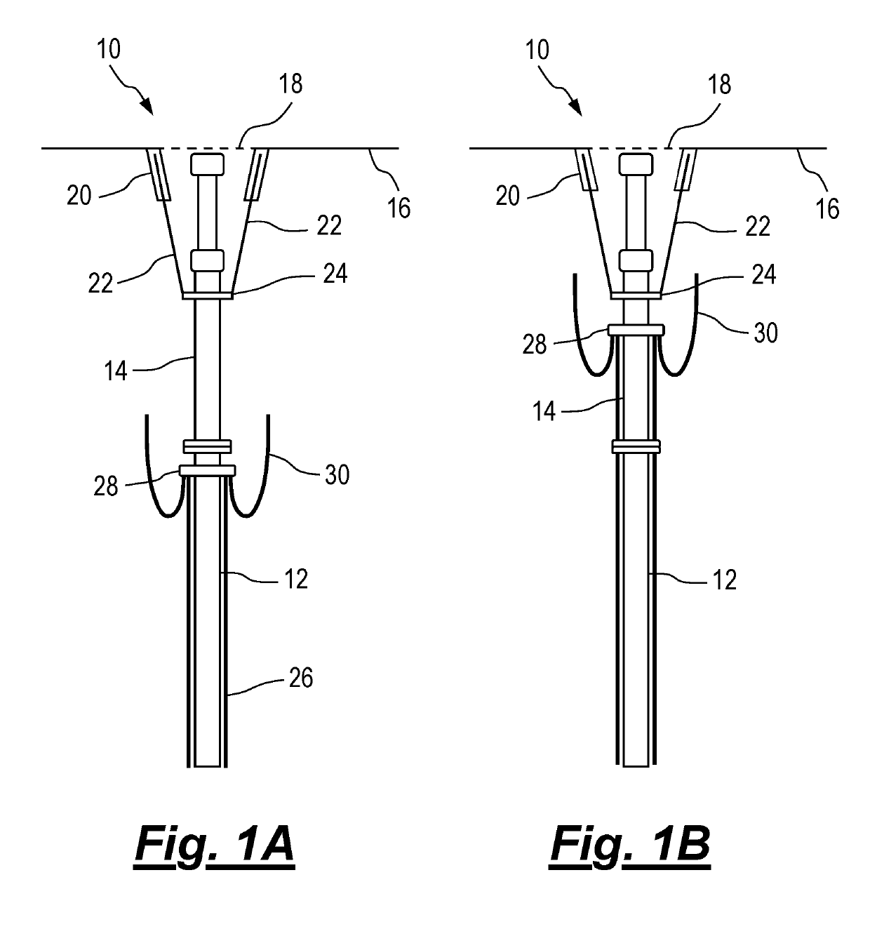
[0207]FIGS. 1A and 1B show features of conventional drilling riser assemblies for extracting oil and natural gas from a subsea reservoir known in the prior art.

[0208]The riser assembly 10 comprises a riser 12 located between a rig platform 16 and a blowout preventer (BOP) assembly (not shown) secured to the top of the wellhead. The riser 12 is connected to a slip joint 14. The slip joint 14 is configured to respond to heave movement of the platform 16 during dynamic sea conditions.

[0209]A portion of platform 16 is shown, which may be a floating rig or drillship. The platform supports the riser assembly 10 and comprises a moon pool opening 18. A plurality of tensioning cylinders 20 are secured to the platform and exert an upward force on rods or cables 22. The lower end of each rod or cable 22 is connected to a riser tensioning ring 24 which is connected to maintain the stability of the riser 12 in the offshore environment.

[0210]External auxiliary lines 26 are connected to the BOP (n...


PUM


Abstract

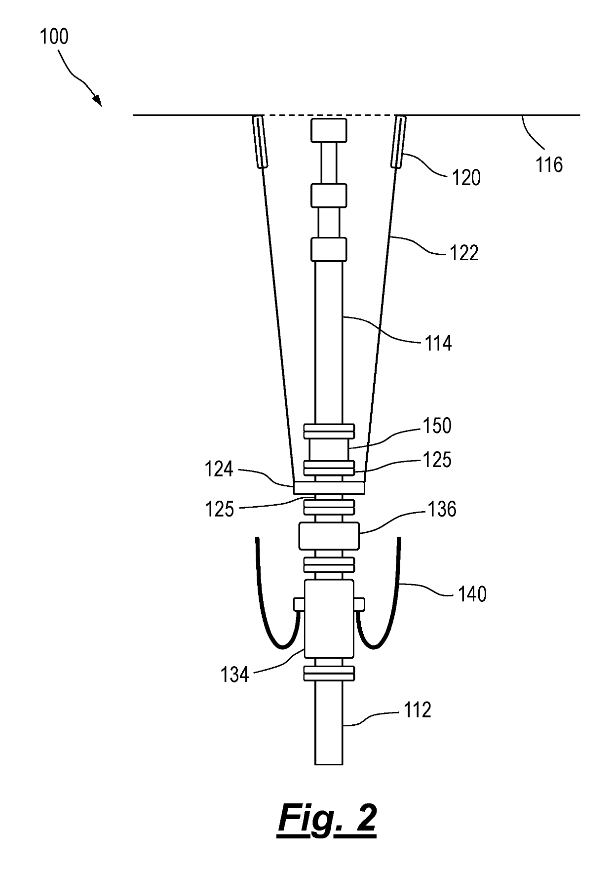
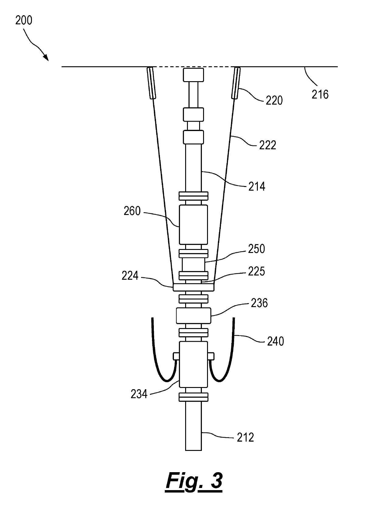
The invention provides a system for handling gas in a riser. The system comprises a riser flow spool, a riser isolation device and an upper riser disconnect assembly wherein at least the riser flow spool is connected to the riser below a riser tension ring and the upper riser disconnect assembly is located above the riser tension ring.

Description

[0001]The present invention relates to a riser gas handling system and method of use, and in particular to riser gas handling systems for subsea applications. A particular aspect of the invention relates to riser gas handling systems that enable managed pressure drilling operations.BACKGROUND TO THE INVENTION[0002]Drilling operations typically use a rotating drill bit on the end of a drillstring. Mud is pumped down the drillstring from a rig mud pumping system and returned to the surface flowing in the annulus between the drillstring and the well. The returning mud exits the annulus above a blow-out preventer (BOP) into a mud return line where it freely flows into solids control equipment to allow sand and cuttings to be removed from the well. The mud is stored in holding tanks until it is pumped back down the well.[0003]The mud which is pumped down the drillstring performs multiple functions, including providing hydraulic power to drilling tools at the end of the drillstring, stabi...

Claims


Application Information

Patent Timeline
Patent Type & Authority Applications(United States)
IPC IPC(8): E21B17/08E21B19/00E21B33/08
CPCE21B17/085E21B19/006E21B33/085E21B17/01E21B21/001
Inventor CLARK, ALAN MURRAYREID, ALAN JOHNALLAN, IAN MCQUEENBIRKETT, GRAHAM PATERSON
Owner DEEP BLUE OIL & GAS LTD
Learn More