
Control of an autonomous vehicle

a technology of autonomous vehicles and control systems, applied in position/direction control, external condition input parameters, instruments, etc., can solve problems such as inability of the driving system to sense its surroundings, requests are not responded to, and the system is not capable, so as to minimise the number of secondary vehicles, minimise the effect of latency

Active Publication Date: 2019-06-13
JAGUAR LAND ROVER LTD
View PDF0 Cites 6 Cited by
  • Summary
  • Abstract
  • Description
  • Claims
  • Application Information

AI Technical Summary

Benefits of technology

The method described in this patent allows for faster and more efficient acquisition of vehicle data by communicating directly with the secondary vehicles or through a remote controller. This helps to coordinate actions between all vehicles and reduces latency. The goal is to get as much data as possible for each vehicle and action, while also minimizing delay and maximizing efficiency.

Problems solved by technology

For example, vehicle sensors upon which the automated driving system relies may be impaired by weather conditions, by dirt or by a fault, therefore compromising the ability of the driving system to sense its surroundings.
Alternatively, the vehicle may enter a complex driving situation that the automated driving system is not capable of handling and so hand back of control to the driver is planned, for example leaving or joining a motorway.
However, although a driver is expected to remain alert to requests from the automated driving system for handing back control, there will inevitably be occasions when such requests are not responded to, for example if the driver has fallen asleep or is unwell.
However, stopping the vehicle may be dangerous in other situations, such as when travelling on a motorway.
Of course, if the reason for handing back control is that the ability of the automated driving system to sense its environment is impaired, deciding the appropriate action to take in the event of a failure of the driver to accept control is particularly challenging.

Method used


Image

  • Control of an autonomous vehicle
  • Control of an autonomous vehicle
  • Control of an autonomous vehicle

Examples


Embodiment Construction

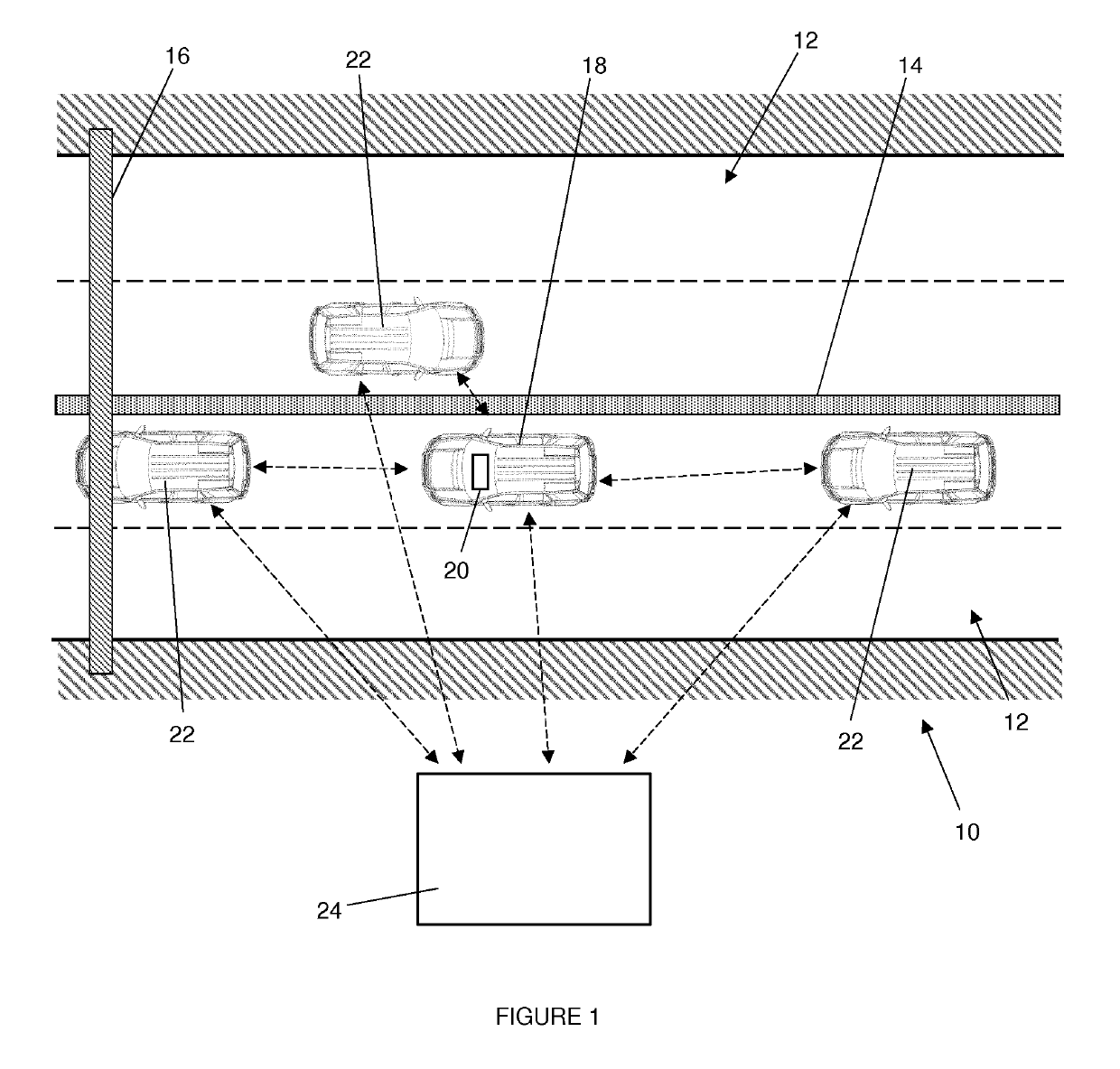
[0037]FIG. 1 shows a typical driving situation on a section of dual-carriageway motorway 10 as an example of a scenario in which methods according to embodiments of the invention may be applied. It should be appreciated, however, that the present invention is not limited to motorway driving, and may find application in all kinds of driving scenarios.

[0038]In the example shown in FIG. 1, the section of motorway 10 includes a pair of two-lane carriageways 12 that are separated by a central reservation 14. Three vehicles occupy the carriageway 12 shown lowermost in FIG. 1, and a fourth vehicle travels in the opposite direction on the uppermost carriageway 12. FIG. 1 also shows a smart gantry 16 spanning the motorway 10.

[0039]The vehicle of interest, hereafter referred to as the primary vehicle 18, is the middle vehicle of the three travelling on the lower carriageway 12. The primary vehicle 18 is a BASt level 3 autonomous vehicle having an automated driving system 20, whereas the other...


PUM


Abstract

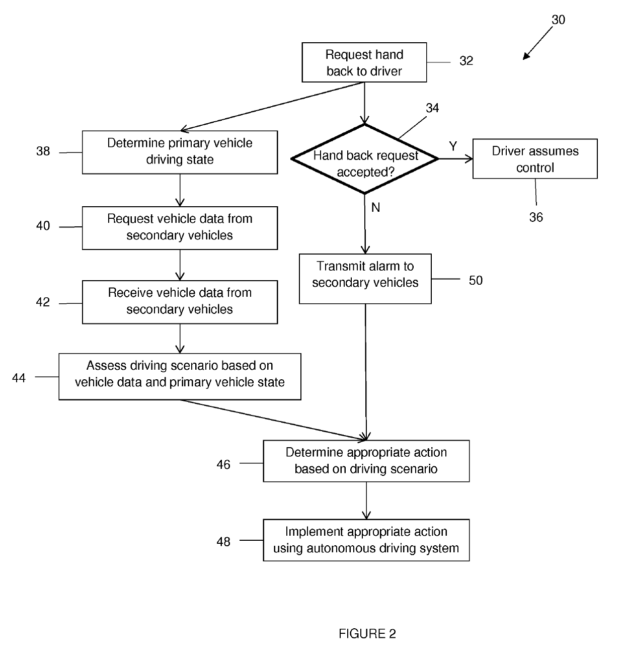
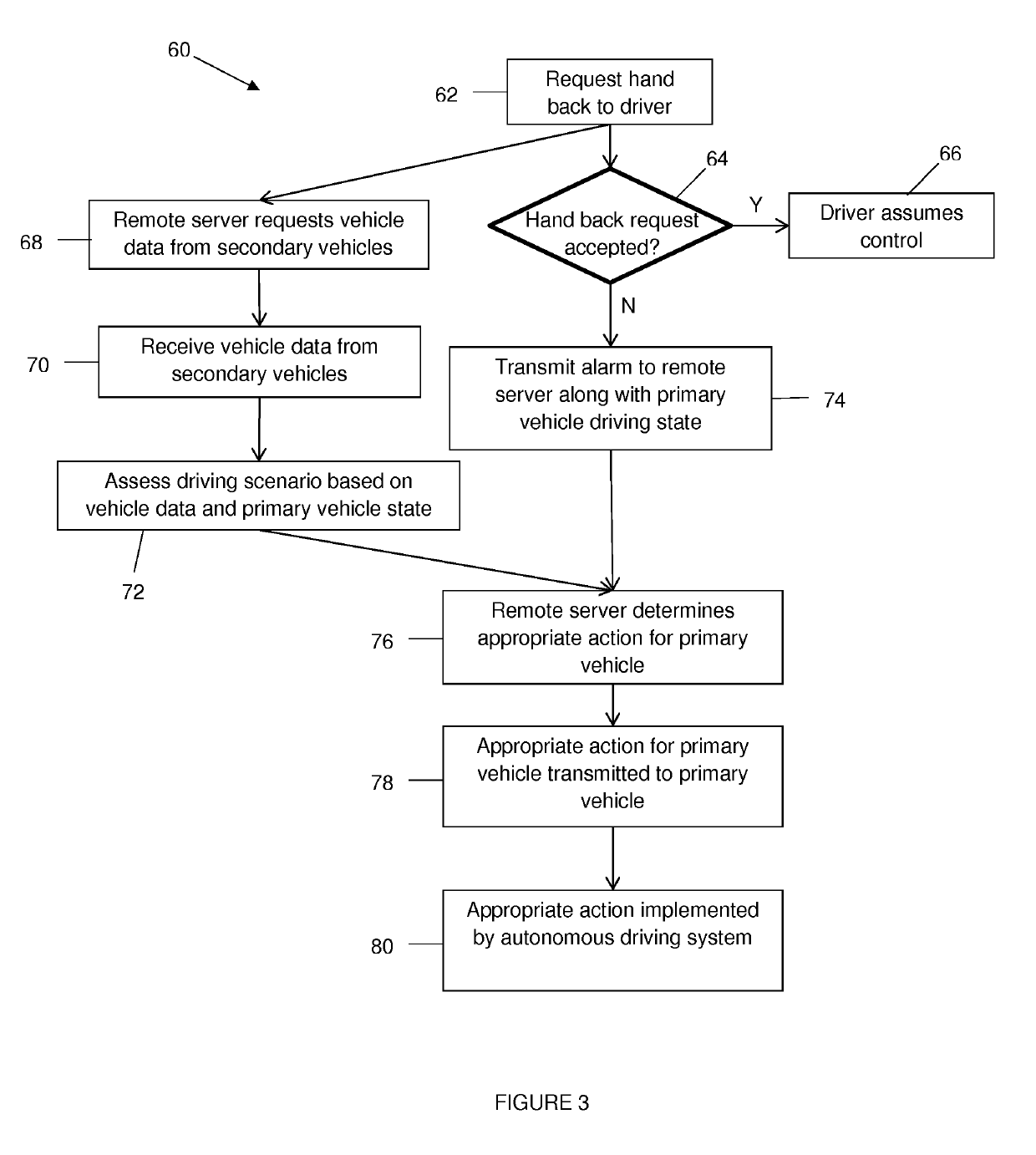
A method of controlling a primary vehicle (18) comprising an automated driving system (20) for driving the primary vehicle autonomously when the primary vehicle is in an autonomous mode, the primary vehicle also being operable manually by a driver when in a manual mode, the method comprising: determining failure of the driver to accept a request to switch the primary vehicle to the manual mode when the vehicle is in the autonomous mode; determining a primary vehicle driving state; acquiring vehicle data for one or more surrounding secondary vehicles (22); determining a contingency action to take with the primary vehicle based on the primary vehicle driving state and the vehicle data for the or each secondary vehicle; and outputting the contingency action to at least one system of the primary vehicle to drive the primary vehicle autonomously in accordance with the determined contingency action.

Description

TECHNICAL FIELD[0001]The present disclosure relates to control of an autonomous vehicle. In particular, but not exclusively, the disclosure relates to control of a BASt level 3 autonomous vehicle. Aspects of the invention relate to a method, to a vehicle controller, to a remote controller and to a vehicle.BACKGROUND[0002]The degree to which operation of a vehicle is automated has been classified into six discrete levels by the Germany Federal Highway Research Institute (BASt). These BASt levels range from level zero, for vehicles having no significant autonomy, to level 5, which designates vehicles that are fully autonomous and in which no driver input is required.[0003]BASt level 3 autonomous vehicles are defined as vehicles in which an automated driving system can handle all aspects of driving, but with the expectation that a human driver will respond appropriately to a request to intervene in certain driving scenarios.[0004]There are various reasons why the automated driving syst...

Claims


Application Information

Patent Timeline
Patent Type & Authority Applications(United States)
IPC IPC(8): G05D1/00B60W50/14G05D1/02
CPCG05D1/0061B60W50/14G05D1/021G05D1/0011G05D2201/0213B60W2050/0077B60W2550/408B60K28/02B60K28/06B60W2556/65B60W2556/45G05D1/0022B60W40/08B60W2040/0818B60W2050/0072B60W2050/0071B60W2050/0075B60W2552/05B60W60/0059B60W2554/80B60W2756/10B60W60/0053B60W50/082B60W50/00B60W2420/403B60W2050/0064B60W2420/408
Inventor MIZUTANI, TOM
Owner JAGUAR LAND ROVER LTD
Learn More