
Constant velocity joint with cooperating boot and shaft vent channels

Active Publication Date: 2019-06-13
NEAPCO INTPROP HLDG LLC
View PDF0 Cites 1 Cited by
  • Summary
  • Abstract
  • Description
  • Claims
  • Application Information

AI Technical Summary

Benefits of technology

The invention provides a CV joint with a venting system that is rigid and has a minimal number of components, which reduces manufacturing costs. This results in a more efficient and economical design.

Problems solved by technology

However, during operation of the vehicle, especially during operation at high temperatures, high internal pressure can build up within the chamber of the CV joint.
The high internal pressure may cause the boot to deform or expand in a manner that can be detrimental to the durability, sealing, or function of the boot, thus minimizing the effectiveness and longevity of the CV joint.
Certain systems and structures used to vent the CV joint are complex and difficult to manufacture.
These complex combinations of channels are not only difficult to manufacture but are prone to deformation as a result of thin cross-sections of the boot created by the vent channels.
The compression and deformation may cause the vent channels to become blocked.
However, the addition of the boot sleeve increases the complexity of assembly by adding components and, as a result, increases manufacturing costs.

Method used


Image

  • Constant velocity joint with cooperating boot and shaft vent channels
  • Constant velocity joint with cooperating boot and shaft vent channels
  • Constant velocity joint with cooperating boot and shaft vent channels

Examples


Embodiment Construction

[0018]The following detailed description and appended drawings describe and illustrate various exemplary embodiments of the invention. The description and drawings serve to enable one skilled in the art to make and use the invention, and are not intended to limit the scope of the invention in any manner. In respect of the methods disclosed, the steps presented are exemplary in nature, and thus, the order of the steps is not necessary or critical.

[0019]As used herein, substantially is defined as “to a considerable degree” or “proximate” or as otherwise understood by one ordinarily skilled in the art. Except where otherwise expressly indicated, all numerical quantities in this description are to be understood as modified by the word “about” and all geometric and spatial descriptors are to be understood as modified by the word “substantially” in describing the broadest scope of the technology. “About” when applied to numerical values indicates that the calculation or the measurement al...


PUM


Abstract

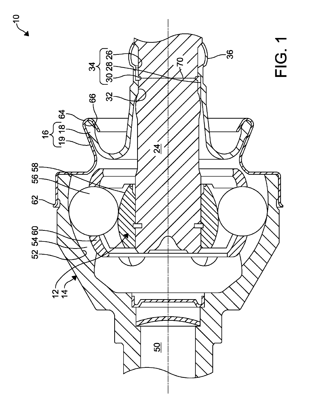
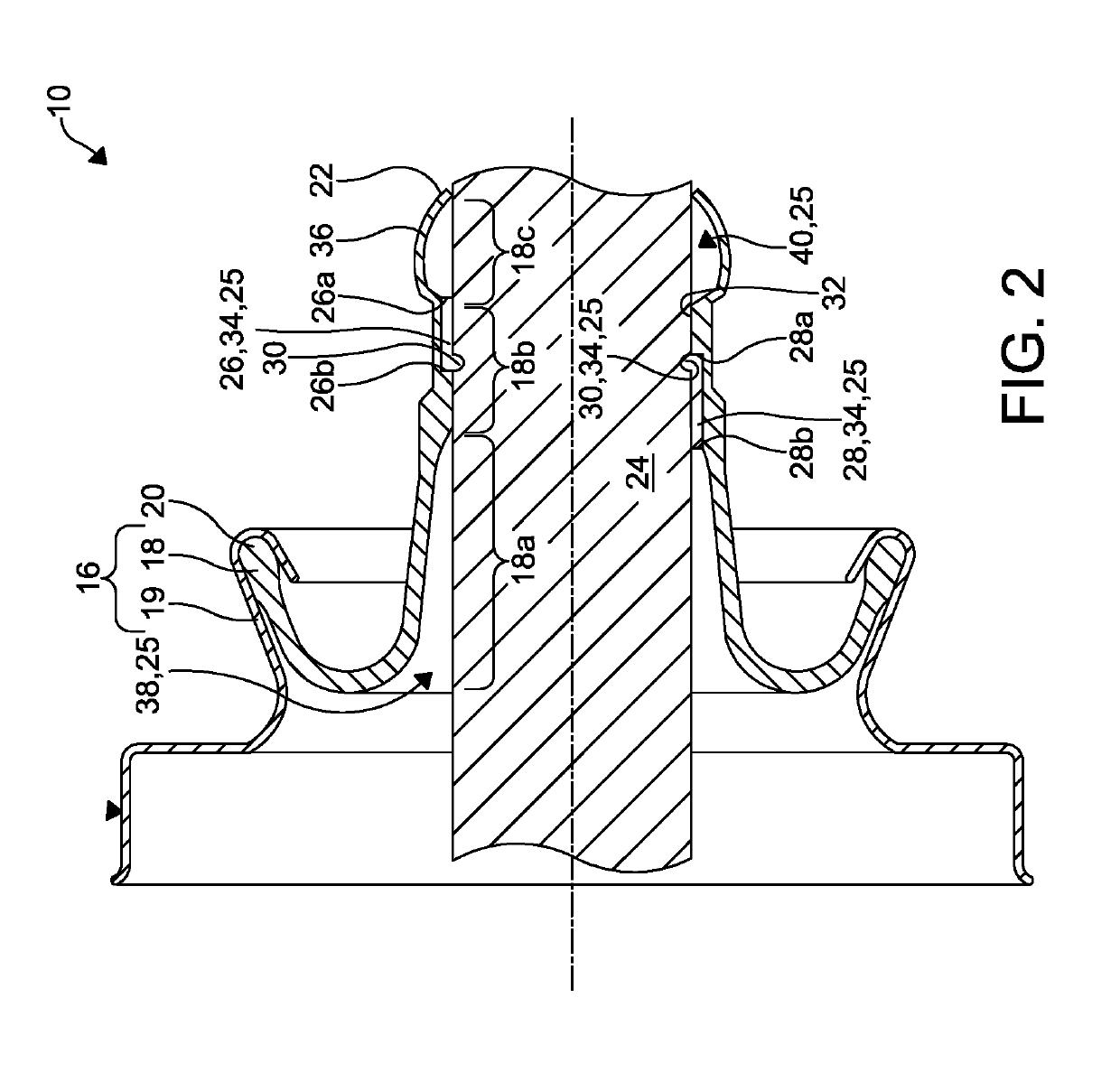
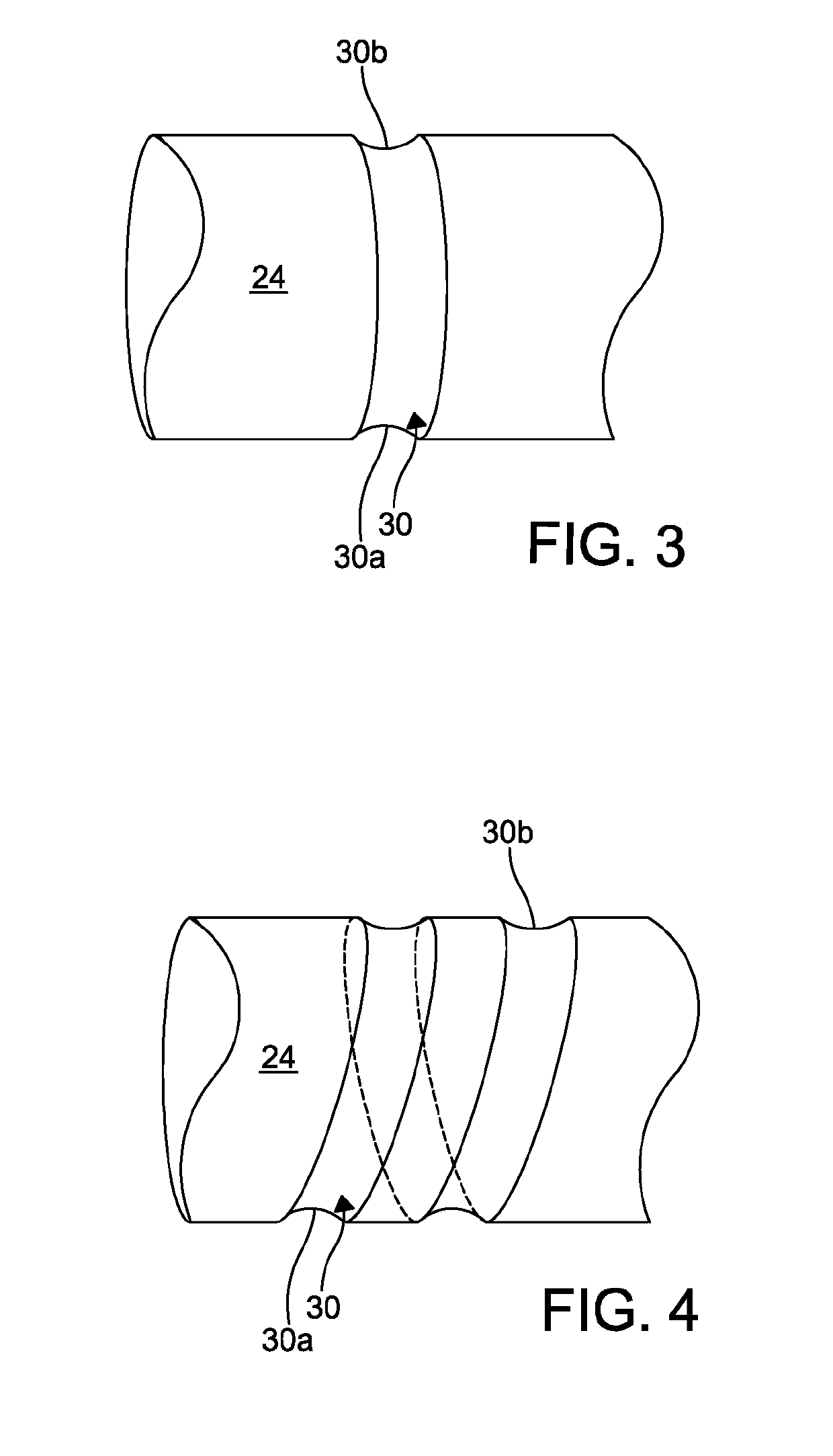
A constant velocity joint includes a shaft and an inner race coupled to the shaft. The inner race has a shaft groove formed thereon. A boot assembly engages the shaft and covers the inner race. A pair of grooves is axially formed in the boot assembly. The shaft groove provides communication between the pair of grooves.

Description

CROSS REFERENCE TO RELATED APPLICATIONS[0001]This application claims the benefit of U.S. Provisional Application No. 62 / 595,850, filed on Dec. 7, 2017. The entire disclosure of the above application is hereby incorporated herein by reference.FIELD[0002]The present invention relates to joint assemblies and more particularly to an assembly for venting elevated pressure within the joint assemblies.BACKGROUND OF THE INVENTION[0003]Joint assemblies such as constant velocity joints are common components in automotive vehicles for applications requiring a transmission of rotating motion such as constant velocity motion. Constant velocity joints (CV joints) are typically used to transmit torque from a transmission of a vehicle to final drive components of the vehicle at a constant velocity or speed.[0004]Common types of CV joints include an outer joint member and an inner joint member. The outer joint member typically includes a hollow chamber which is open at one end and closed at an oppos...

Claims


Application Information

Patent Timeline
IPC IPC(8): F16D3/84F16D3/223
CPCF16D3/845F16D3/223F16D2003/846F16D2003/22316Y10S277/928
Inventor DUBIEL, NICKWEHNER, ROBERT J.HOPSON, MICHAEL
Owner NEAPCO INTPROP HLDG LLC
Learn More