
Oscillating sprinkler with adjustable spray area

a technology of oscillating sprinkler and spray area, which is applied in the field of oscillating sprinkler with adjustable spray area, can solve the problems of unadjustable spray area of sprinkler, limited use function, and complicated structure design of oscillating sprinkler, and achieves flexibility in adjustment operation, simple structure design, and convenient use

Inactive Publication Date: 2019-06-06
NINGBO DAYE GARDEN IND
View PDF45 Cites 5 Cited by
  • Summary
  • Abstract
  • Description
  • Claims
  • Application Information

AI Technical Summary

Benefits of technology

The present invention solves a problem in the prior art by providing an improved oscillating sprinkler with an adjustable spray area. The sprinkler has a simple structure design, flexible adjustment operation, and is convenient to use. It is capable of precisely controlling adjustment of the spray area at a low production cost. The technical effect of the invention is to overcome the disadvantage of prior art and provide an improved sprinkler with an adjustable spray area.

Problems solved by technology

Such oscillating sprinkler has an unadjustable spray area, and a use function is limited.
However, additionally providing the adjusting valve on the oscillating sprinkler not only causes a structure design of the oscillating sprinkler more complex but also increases production costs.
Especially, because an operation of the adjusting valve is a blind operation, it is difficult to precisely control an adjustment change of the spray area, and the spray range can only be roughly grasped.
This also brings some inconvenience to use.

Method used


Image

  • Oscillating sprinkler with adjustable spray area
  • Oscillating sprinkler with adjustable spray area
  • Oscillating sprinkler with adjustable spray area

Examples


Embodiment Construction

[0019]The following further describes embodiments of the present invention in detail with reference to the accompanying drawings.

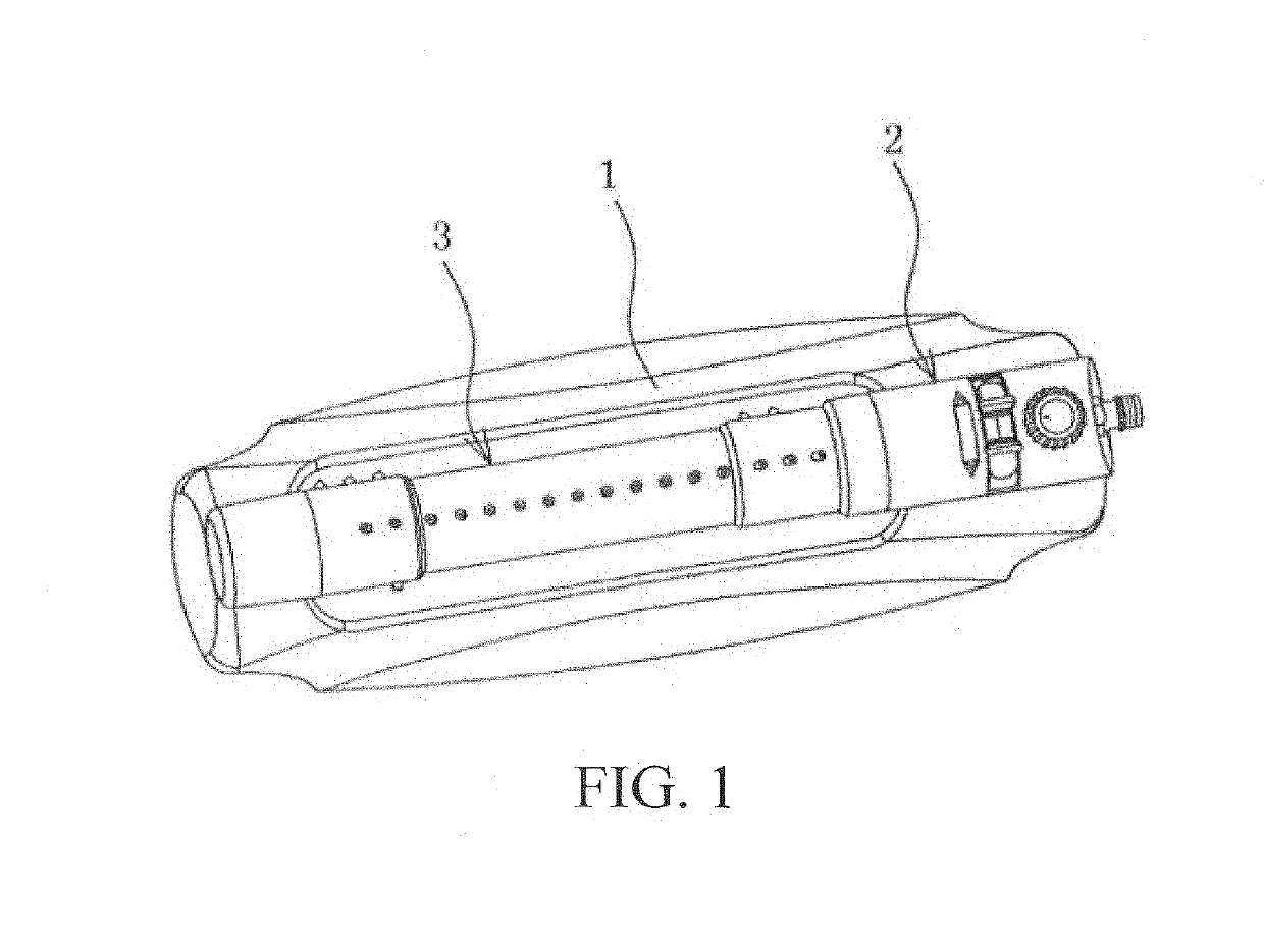
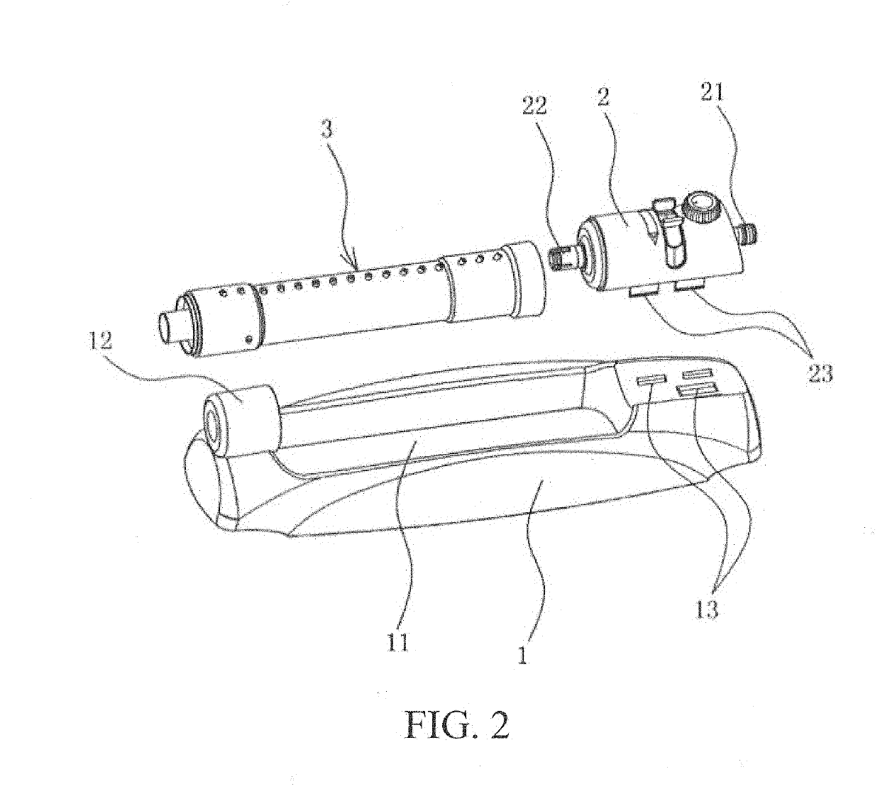
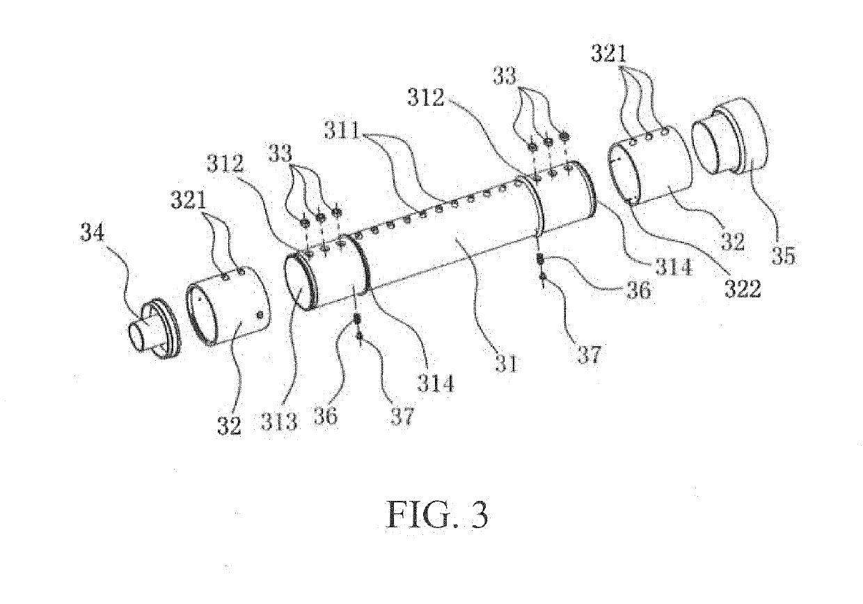
[0020]As shown in FIG. 1 to FIG. 3: 1: Base; 11: Groove; 12: Shaft seat; 13: Engagement hole; 2: Oscillating gear box; 21: Water inlet end; 22: Water outlet end; 23: Elastic engagement plate; 3: Spray assembly; 31: Spray tube; 311: Fixed spray hole; 312: Water passage holes; 313: Water cavity; 314: Shoulder; 32: Adjusting jacket; 321: Adjusting spray holes; 322: Positioning slot; 33: Sealing ring; 34: Plug shaft; 35: Connection sleeve; 36: Spring; and 37: Positioning ball.

[0021]As shown in FIG. 1 and FIG. 2, an oscillating sprinkler with an adjustable spray area obtains a coverage spray area by swinging an ejected water flow left and right in a range of 90 degrees by using a jet principle related to flow pressure, so as to facilitate irrigation and maintenance of gardens, nurseries, lawns, and the like, temperature reduction for building roofs, pavement co...


PUM


Abstract

The present invention discloses an oscillating sprinkler with an adjustable spray area, and relates to a gardening watering tool that obtains a spray area by swinging an ejected water flow by using a jet principle related to flow pressure. A structure of the oscillating sprinkler includes a base, an oscillating gear box, a spray assembly, and the like. An end portion of a spray tube of the spray assembly is mainly provided with water passage holes in communication with a water cavity in the spray tube and an adjusting jacket rotatably sleeved over the end portion of the spray tube and sealing the water passage holes. A plurality of rows of adjusting spray holes with different quantities is provided on the adjusting jacket, and the plurality of rows of adjusting spray holes can be in sequentially selective communication with the water passage holes with rotation of the adjusting jacket. Therefore, when original fixed spray holes on the spray tube and the adjusting spray holes that can be adjusted at the end portion of the spray tube are combined for use, the entire oscillating sprinkler has a function of controlling adjustment of the spray area. The improved oscillating sprinkler further has advantages such as simplicity in structure design, flexibility in adjustment operation, convenience in use, being capable of precisely controlling adjustment of the spray area, and low production costs.

Description

TECHNICAL FIELD[0001]The present invention relates to an oscillating sprinkler in watering tools for garden greening, and specifically, to an oscillating sprinkler with an adjustable spray area.RELATED ART[0002]An oscillating sprinkler is a common watering tool in garden greening, and sprays a coverage area by swing left and right in a range of 90 degrees mainly by using a jet principle related to flow pressure. Therefore, the oscillating sprinkler may be widely applied to irrigation and maintenance of gardens, nurseries, lawns, and the like, or may be applied to temperature reduction for building roofs, and also has obvious effects in scenarios such as pavement construction maintenance and dust and coal dust treatment. A common oscillating sprinkler is shown as the disclosed “Gardening Spray Apparatus” with the Chinese Patent No. 200720184467.1. A structure of the gardening spray apparatus mainly includes a base, a spray assembly mounted on the base, an oscillating gear box driving...

Claims


Application Information

Patent Timeline
Patent Type & Authority Applications(United States)
IPC IPC(8): B05B3/04B05B15/68
CPCB05B3/044B05B15/68B05B1/20A01G25/02B05B3/14
Inventor YE, XIAODONGHUANG, JIFENG
Owner NINGBO DAYE GARDEN IND
Learn More