
Biomagnetism measuring device

a biomagnetism and measuring device technology, applied in the field of biomagnetism measuring devices, can solve the problems of insufficient use, difficult to change the arrangement of squid sensors, replace or remove squid sensors, etc., and achieve the effect of accurate detection of biomagnetism regardless

Active Publication Date: 2019-06-06
NAT UNIV CORP TOKYO MEDICAL & DENTAL UNIV +1
View PDF0 Cites 4 Cited by
  • Summary
  • Abstract
  • Description
  • Claims
  • Application Information

AI Technical Summary

Benefits of technology

The invention is a device that can accurately measure biomagnetism, which is the magnetism produced by living organisms. This device can measure biomagnetism from any subject, making it highly versatile and useful in a variety of applications.

Problems solved by technology

Therefore, SQUID sensors must be provided in a dewar that stores refrigerant, which makes it difficult for SQUID sensors to make close contact with a body in order to detect biomagnetism.
Therefore, it is difficult to change the arrangement of SQUID sensors and replace or remove SQUID sensors.
Therefore, SQUID sensors have a problem in that, despite being high-precision magnetic sensors, they cannot be used close enough to the body and are difficult to handle.

Method used


Image

  • Biomagnetism measuring device
  • Biomagnetism measuring device
  • Biomagnetism measuring device

Examples


Embodiment Construction

[0039]An embodiment of the present invention is described in detail below, but the present invention is not limited to the following embodiment and may be changed as appropriate without departing from the object of the present invention.

1>

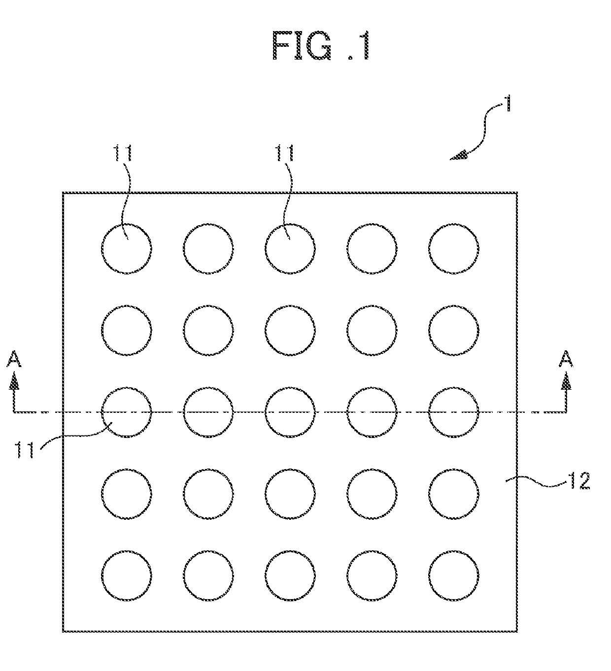
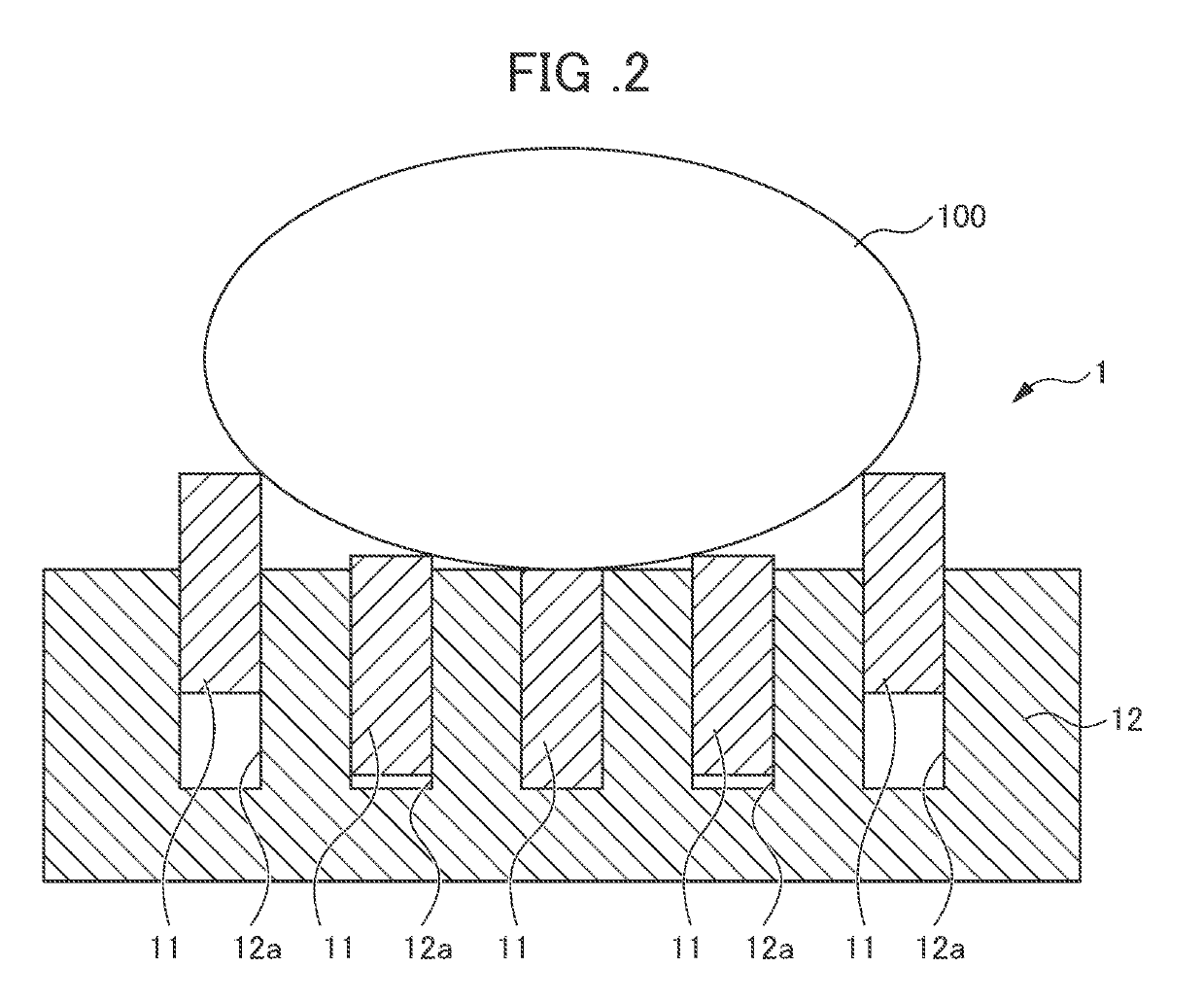
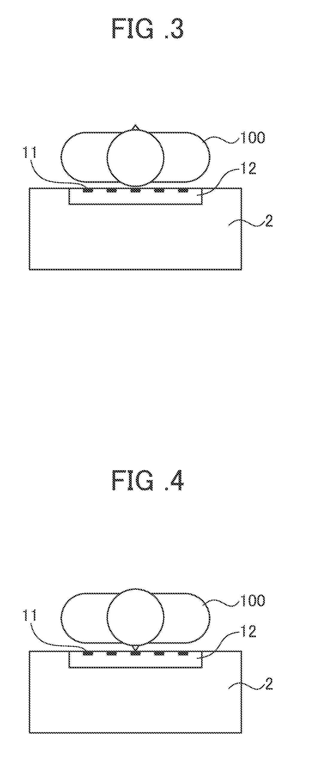
[0040]FIG. 1 is a plan view for illustrating an example of a biomagnetism measuring device according to an embodiment of the present invention. FIG. 2 is a schematic view for explaining the positional relationship between a subject and magnetic sensors of the biomagnetism measuring device and is a cross-section taken along the line A-A′ in the biomagnetism measuring device illustrated in FIG. 1. As illustrated in FIGS. 1 and 2, the biomagnetism measuring device 1 includes a plurality of magnetic sensors 11 that detect biomagnetism, a retaining portion 12 formed with retaining holes 12a that hold the magnetic sensors 11 such that the magnetic sensors 11 can move freely and a movement mechanism configured to move detection surfaces of the magnetic se...


PUM


Abstract

The objective of the present invention is to provide a biomagnetism measuring device capable of accurately detecting biomagnetism regardless of the object to be measured. This biomagnetism measuring device (1) is provided with: a plurality of magnetic sensors (11) which detect biomagnetism of a living body (100); a retaining portion (12) including retaining holes (12a) which retain the plurality of magnetic sensors (11) with freedom to move individually; and a movement mechanism which moves the magnetic sensors (11) individually in a contacting / separating direction causing the magnetic sensors (11) to come into contact with or separate from the living body (100). As movement mechanisms there may be mentioned, for example, a pneumatic / hydraulic mechanism (20), a resilient body mechanism (30), a screw mechanism (40) and a gear mechanism (50).

Description

TECHNICAL FIELD[0001]The present invention relates to a biomagnetism measuring device that uses magnetic sensors.BACKGROUND ART[0002]As a magnetic sensor that detects magnetism, there is conventionally known a magneto resistive (MR) sensor which uses a magneto resistive element (MR element). Direct current resistance acting on the MR element fluctuates according to the strength of the magnetic field. The MR sensor detects magnetic field variance or the presence of magnetic material as a change in voltage using the degree of fluctuation of the direct current resistance.[0003]MR sensors are widely used as magnetic heads in hard disc devices, rotation sensors (encoders) and position sensors. Further, in recent years, the widespread use of mobile devices such as smartphones and tablet devices has led to such mobile devices being provided with an orientation sensor that has an MR sensor which uses geomagnetism to measure orientation. The information obtained from the orientation sensor i...

Claims


Application Information

Patent Timeline
Patent Type & Authority Applications(United States)
IPC IPC(8): A61B5/04A61B5/00
CPCA61B5/04005A61B5/6843G01R33/04G01R33/09G01R33/063A61B5/05G01R33/02A61B5/242A61B5/0205A61B5/0816A61B5/251A61B5/25
Inventor KAWABATA, SHIGENORIFUKUI, TAKATOSHIBUYA, TOMOHIKO
Owner NAT UNIV CORP TOKYO MEDICAL & DENTAL UNIV
Learn More