
Augmented reality method and system for design

a technology of augmented reality and design software, applied in the field of augmented reality method and system for design, can solve the problems of inability to enter the initial design idea into the system, the task of inputting the initial design model is an ever-present obstacle to many users beginning work on their design, and the user of such design software is presented with a blank page at the start, so as to save time

Active Publication Date: 2019-05-30
PEJIC PETAR +1
View PDF8 Cites 20 Cited by
  • Summary
  • Abstract
  • Description
  • Claims
  • Application Information

AI Technical Summary

Benefits of technology

The present invention provides a system and method for generating formal designs using several sources of input without requiring a single input method. The system automates several design input tasks, which saves time and allows the end user to input a design quickly and easily. The software also highlights best design practices and is comfortable for the end user as it requires no prior knowledge of computer-aided design software. The informal sketch by the user is used as the initial input of the design, which is convenient for the end user as they may not require a formal input. The system also allows the end user to sketch an informal design away from a computer, using a photograph or scan of a sketch on paper. Overall, the technical effects of the invention are that it improves efficiency and ease of use for the end user.

Problems solved by technology

The entry of the initial design idea into a system is a considerable obstacle.
However, the task of inputting the initial model of the design is an ever-present obstacle to many users beginning work on their design.
While the details of operation have changed, and some features such as three dimensional modeling are quite impressive, inevitably the user of such design software is presented with a blank page at start.
Other users that persevere and attempt to use the software may inadvertently use the design tools in an unintended way, resulting in a design that is frustratingly incorrect or entirely impossible.
The system will attempt to model a design that does not follow best practices, is not safe, or is not commercially feasible.
While this solution will provide the users guidance to begin the work, it does not overcome the problems associated with learning an unfamiliar system.
An additional tradeoff is that the users no longer have full flexibility in their design, without first extensively customizing the provided template.
This significantly decreases the benefit of the design software.

Method used


Image

  • Augmented reality method and system for design
  • Augmented reality method and system for design
  • Augmented reality method and system for design

Examples


example interface

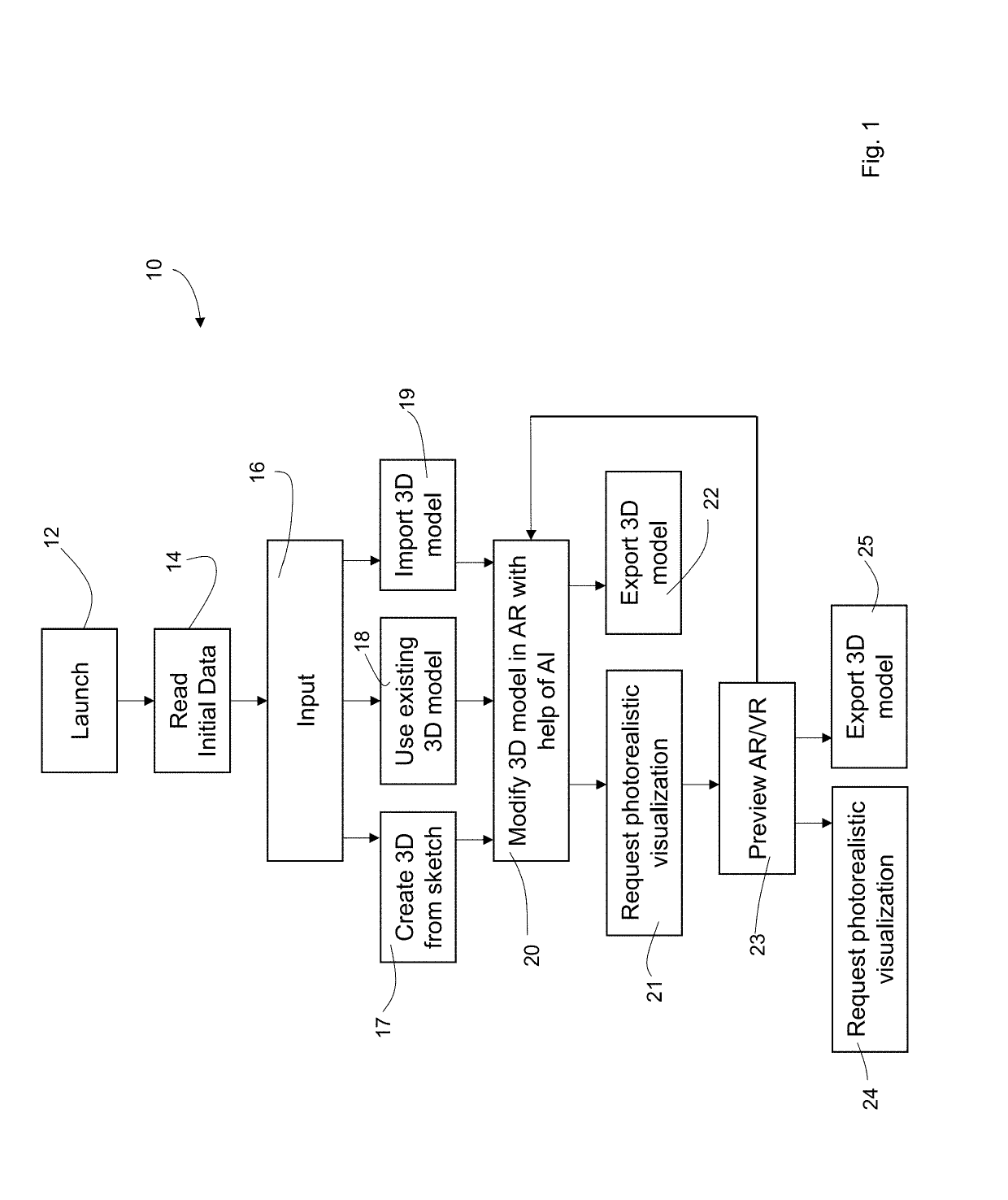
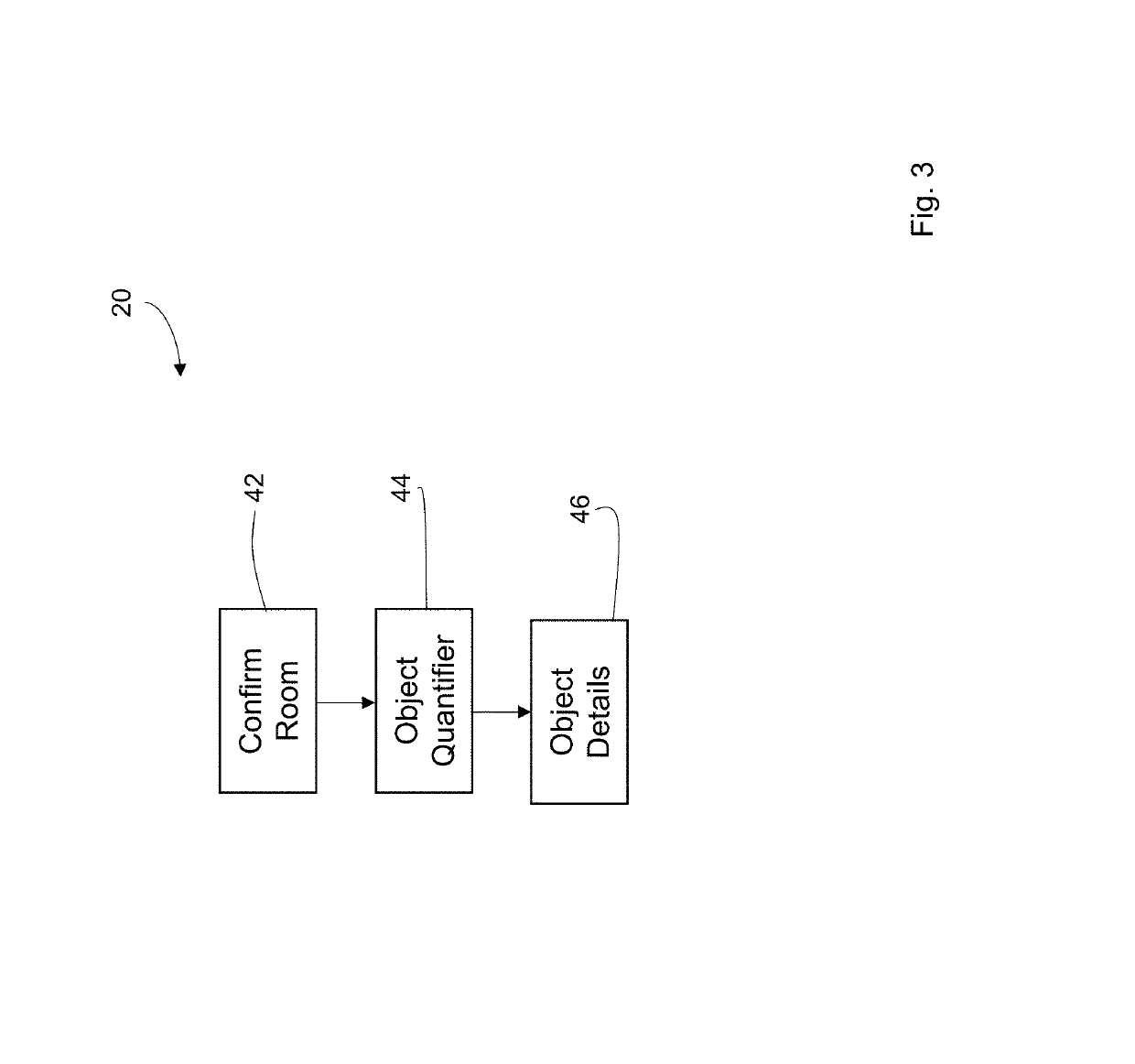
[0097]A sample user interface is shown in FIG. 4. As shown in FIG. 4, the system 10 interface shows the step 18 of confirming the layout. The interface is shown on a portable device 60. The system 10 is showing the preliminary design 62 as super-imposed on a photo of the two-dimensional sketch 64. The sketch 64 is drawn on a sheet of paper 66. The sketch fits within the boundaries of the device 60 screen 68.

[0098]Three phases of the system are depicted inFIGS. 5A-C. First, as shown in FIG. 5A, the end user draws an informal two-dimensional sketch 82 on a piece of paper 84 using a high-contrast marking instrument 86, such as a marker.

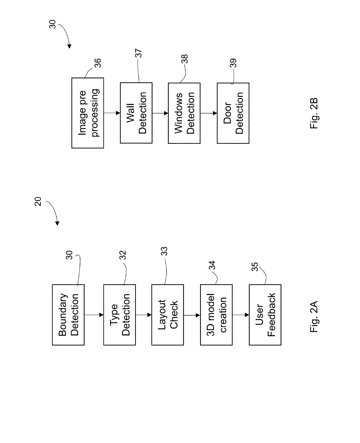
[0099]Second, in FIG. 5B, the end user takes a photo of the sketch using a portable device 90, such as a cell phone. The phone accepts the input of the paper-based sketch 84 and displays the input to the user 92, already rotated and de-skewed. Finally, as shown in FIG. 5C, a three-dimensional design 98 is shown to the end user, following the detection 20...

process example

Design Process Example

[0101]FIGS. 7A-F depict an overview of the design process using one embodiment of the invention. As shown in FIG. 7A, the process begins with a sheet of paper 112 on a work surface 110 such as a table shown in FIG. 7A. The end user draws a sketch 114 on the paper 112 using a suitable writing utensil 116. While the sketch shown in FIG. 7A depicts features such as doors and windows in a formal manner akin to an architectural drawing, the system accepts as input an informal drawing where the doors and windows are indicated in any number of possible ways. The system is able to infer which user-selected symbols indicate a door or window.

[0102]In one embodiment, the system indicates to the end user if a particular room is unreachable or if too many rooms lack windows as these may indicate that the design is incomplete.

[0103]Further, while the sketch 114 shown in FIG. 7A appears formal, it nonetheless is lacking many architectural details that are not required by the ...


PUM


Abstract

A system for generating formal premises designs is discussed. The system begins by inputting an informal two-dimensional rendering of the premises. The system continues by analyzing the informal two-dimensional rendering and determining features found on the premises depicted by the two-dimensional rendering. The system then generates a three-dimensional model of the premises and populates it with interactive objects. Finally, the system provides multiple views of the three-dimensional rendering containing interactive objects.

Description

BACKGROUND OF THE INVENTION1. Field of the Invention[0001]This invention is directed to a method and system for aiding in design using augmented reality and virtual reality components.2. Background of the Invention[0002]Many design tasks have seen only incremental improvements stemming from computerization. On the one hand, computerization has ended the days of manual drafting and re-drafting of designs. On the other hand, the steps which occur before the design stage are not significantly different than they would have been without a computer. Mainly, a rough sketch is entered into a formal system which then proceeds to perform the three-dimensional modeling.[0003]The entry of the initial design idea into a system is a considerable obstacle. The end user of the design software must become competent in use of the software. Different vendors take various approaches to the design input stage, and some are more successful at simplifying the task than others. However, the task of inputt...

Claims


Application Information

Patent Timeline
Patent Type & Authority Applications(United States)
IPC IPC(8): G06T17/05G06T19/00G06T19/20G06K9/00G06F17/50
CPCG06T17/05G06T19/006G06T19/20G06K9/00476G06F17/5004G06T2210/04G06T2200/24G06T2219/2004G06T2219/2024G06T2219/2012G06T19/00G06V30/422G06T7/00G06T7/543G06F30/13G06F2111/18
Inventor PEJIC, PETARBAVASTRO, FREDERIC
Owner PEJIC PETAR
Learn More