Carriage moving mechanism and liquid discharge apparatus

Active Publication Date: 2019-05-30
SEIKO EPSON CORP
View PDF0 Cites 0 Cited by
  • Summary
  • Abstract
  • Description
  • Claims
  • Application Information

AI Technical Summary

Benefits of technology

The patent text discusses ways to prevent deformation in a support member and enhance productivity in a liquid discharge apparatus. It explains that by using a third support member with rigidity, the risk of deformation in the first axis is reduced. However, when the distance between the second and first support members is long and the dimension of the third support member in the first axis is large, bending deformation can occur in the third support member. Additionally, the text describes a configuration wherein the first liquid is discharged from both the first and second liquid discharge heads, making the area of liquid discharge wider and improving productivity. It also mentions that the configuration helps prevent the photocurable ink from spreading or bleeding.

Problems solved by technology

However, when the liquid discharge apparatus is made large in size and the frame is made long in length, the distance between the point of action of the frame and the fulcrum of the frame is longer, and the moment that acts on the frame are enlarged, and thus the frame may be deformed.
When the third support member is made deformed, the positions of the driving pulley and the driven pulley change, and a deformation (e.g., a deflection) of the annular belt occurs, and it becomes hard to cause the first carriage to move properly in the first axis.
Then, it becomes hard for the liquid discharge apparatus to cause the first liquid discharge head to move properly in the first axis, and quality of the image to be printed on the medium M may degrade.

Method used


Image

  • Carriage moving mechanism and liquid discharge apparatus
  • Carriage moving mechanism and liquid discharge apparatus
  • Carriage moving mechanism and liquid discharge apparatus

Examples


exemplary embodiment 1

Overview of Printer

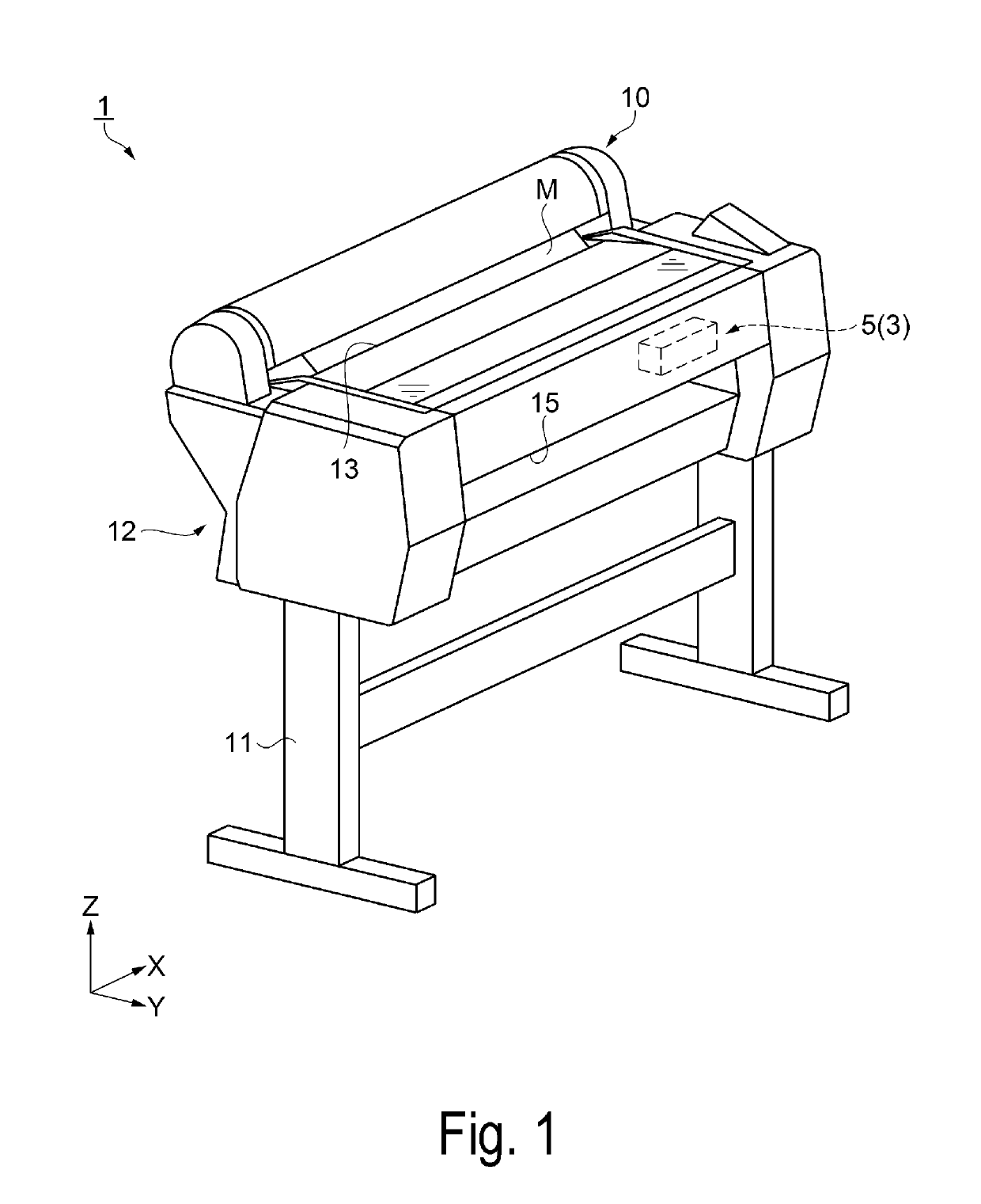
[0040]FIG. 1 is a perspective view of a printer according to Exemplary Embodiment 1.

[0041]First of all, an overview of the printer 1 according to Exemplary Embodiment 1 is described below with reference to FIG. 1.

[0042]As illustrated in FIG. 1, the printer 1 according to Exemplary Embodiment 1, which is an example of the “liquid discharge apparatus”, is a large-format printer (LFP) that prints images on, for example, a single-cut sheet having a large sheet size such as A1-sized sheet of JIS standard, a roll paper having the same width as the single-cut sheet, and the like.

[0043]The printer 1 includes a pair of leg portions 11, a casing portion 12 substantially formed in a rectangular parallelepiped shape supported by the leg portion 11, a setting portion 10 for feeding a medium M to the casing portion 12, and a carriage moving mechanism 3 described below (see FIG. 2). For example, cloth such as polyester, paper, resin film, and the like can be used for the medium ...

exemplary embodiment 2

[0113]FIG. 9 and FIG. 10 are schematic views illustrating a configuration of the carriage moving mechanism to be loaded on the printer according to Exemplary Embodiment 2.

[0114]More specifically, FIG. 9, which is a view corresponding to FIG. 2, is a plan view of a carriage moving mechanism 3A from the Z axis side. FIG. 10, which is a view corresponding to FIG. 4, is a plan view of the carriage moving mechanism 3A from the X axis side.

[0115]The carriage moving mechanism 3 to be loaded on the printer 1 according to Exemplary Embodiment 1 has the same configuration, except for the shape of the third support member, as the carriage moving mechanism 3A to be loaded on a printer 1A according to Exemplary Embodiment 2. That is, a third support member 60A according to Exemplary Embodiment 2 has a longer dimension in the Y axis than the third support member 60 according to Exemplary Embodiment 1. This is the main difference between Exemplary Embodiment 2 and Exemplary Embodiment 1.

[0116]Here...

exemplary embodiment 3

[0130]FIG. 11, which is a view corresponding to FIG. 2, is a schematic view illustrating a configuration of the carriage moving mechanism to be loaded on the printer according to Exemplary Embodiment 3.

[0131]A carriage moving mechanism 3B to be loaded on a printer 1B according to Exemplary Embodiment 3 includes two carriages 55 and 56. The carriage moving mechanism 3 to be loaded on the printer 1 according to Exemplary Embodiment 1 includes one carriage 55. This is the main difference between Exemplary Embodiment 3 and Exemplary Embodiment 1.

[0132]Hereinafter, an overview of the printer 1B according to Exemplary Embodiment 3 is described with reference to FIG. 11, focusing on the differences from Exemplary Embodiment 1. Here, the components that are the same as the components in Exemplary Embodiment 1 are referenced using like numbers, and no descriptions for such components are provided below.

[0133]As illustrated in FIG. 11, the carriage 55, as an example of the “first carriage” is...


PUM


Abstract

A carriage moving mechanism including a driving unit including a driving pulley, a driving motor, and a first support member for supporting both the driving pulley and the driving motor, a driven unit including a driven pulley and a second support member for supporting the driven pulley, and a third support member supporting both the driving unit and the driven unit, an annular belt that is wound around both the driving pulley and the driven pulley, a first outer peripheral surface and a second outer peripheral surface facing to the first outer peripheral surface, and a first carriage that is attached to the first outer peripheral surface, wherein the second support member, the third support member, and the first support member are aligned in this order in a first axis, and the third support member is disposed inside the annular belt.

Description

BACKGROUND1. Technical Field[0001]The invention relates to a carriage moving mechanism and a liquid discharge apparatus having the carriage moving mechanism.2. Related Art[0002]For example, a printer (a liquid discharge apparatus) described in JP-A-2015-150749 includes a carriage on which a recording head is loaded, a driving pulley and a driven pulley, a driving motor for supporting and driving the driving pulley, a support member for rotatably supporting the driven pulley, a belt that is wound around both the driving pulley and the driven pulley, a biasing member for providing a predefined tension (a tensional force) to the belt, and a frame for supporting both the driving motor and the support member. A driving pulley (a driving motor) is attached to one end of the frame, a driven pulley (a support member) is attached to the other end of the frame, and the driving pulley and the driven pulley are disposed on a surface at one side of the frame. The frame supports the driving pulle...

Claims


Application Information

Patent Timeline
IPC IPC(8): B41J19/20B41J19/00B41J2/21
CPCB41J19/202B41J19/005B41J2/2103B41J2/2114
Inventor MURAYAMA, OSAMU
Owner SEIKO EPSON CORP
Why Eureka
Try Eureka