
Precision multi-view display

a multi-view display and display system technology, applied in the field of multi-view display systems, can solve the problems of limited multi-view displays, difficult to target images to a particular location, and significant limitations of display systems

Active Publication Date: 2019-05-16
MISAPPLIED SCI INC
View PDF0 Cites 43 Cited by
  • Summary
  • Abstract
  • Description
  • Claims
  • Application Information

AI Technical Summary

Benefits of technology

The patent is about a new system that can show different things to different people at the same time over a wider view. The system can be made up of smaller screens placed together, and there are techniques to make this process easier. There is also a calibration process to make sure that the screens show the right thing in the correct place. The system has a simple interface that allows people to specify which parts of the display they want to see.

Problems solved by technology

There are significant limitations to the display system 2700.
Targeting images to a particular location becomes increasingly challenging.
Due to these and other limitations, current multi-view displays are typically limited to a very small number of viewing zones.
This technique depends on the limited ability of the human eye to resolve this level of detail.
Unfortunately, the lenticules act as magnifiers, and can make the sub-pixels quite evident.
Lenticular displays that use cylindrical lenses are limited to creating views in a single dimension, e.g., strictly horizontal or strictly vertical.
Unfortunately, there is no equivalent trick to angling the lenticules to allow sub-pixel mixing because both dimensions are magnified.
There are also techniques using parallax barriers, but those techniques lose significant brightness.
Steerable backlights combined with time division multiplexed display have also been disclosed, but the number of views of such a system is limited by the lack of high speed liquid crystal display (LCD) panels.
There are disadvantages to tiling a display versus simply building a larger one.
Although independent multi-view displays can be arranged to create the appearance of a larger display, the multi-view displays used to make such a tiled display do not include any features to make this sort of tiled display easier to construct or less costly.
Finally, most electronic multi-view displays are targeted at auto-stereo applications, and do not provide an interface for arbitrarily directing arbitrary content to multiple locations simultaneously.

Method used


Image

  • Precision multi-view display
  • Precision multi-view display
  • Precision multi-view display

Examples


Embodiment Construction

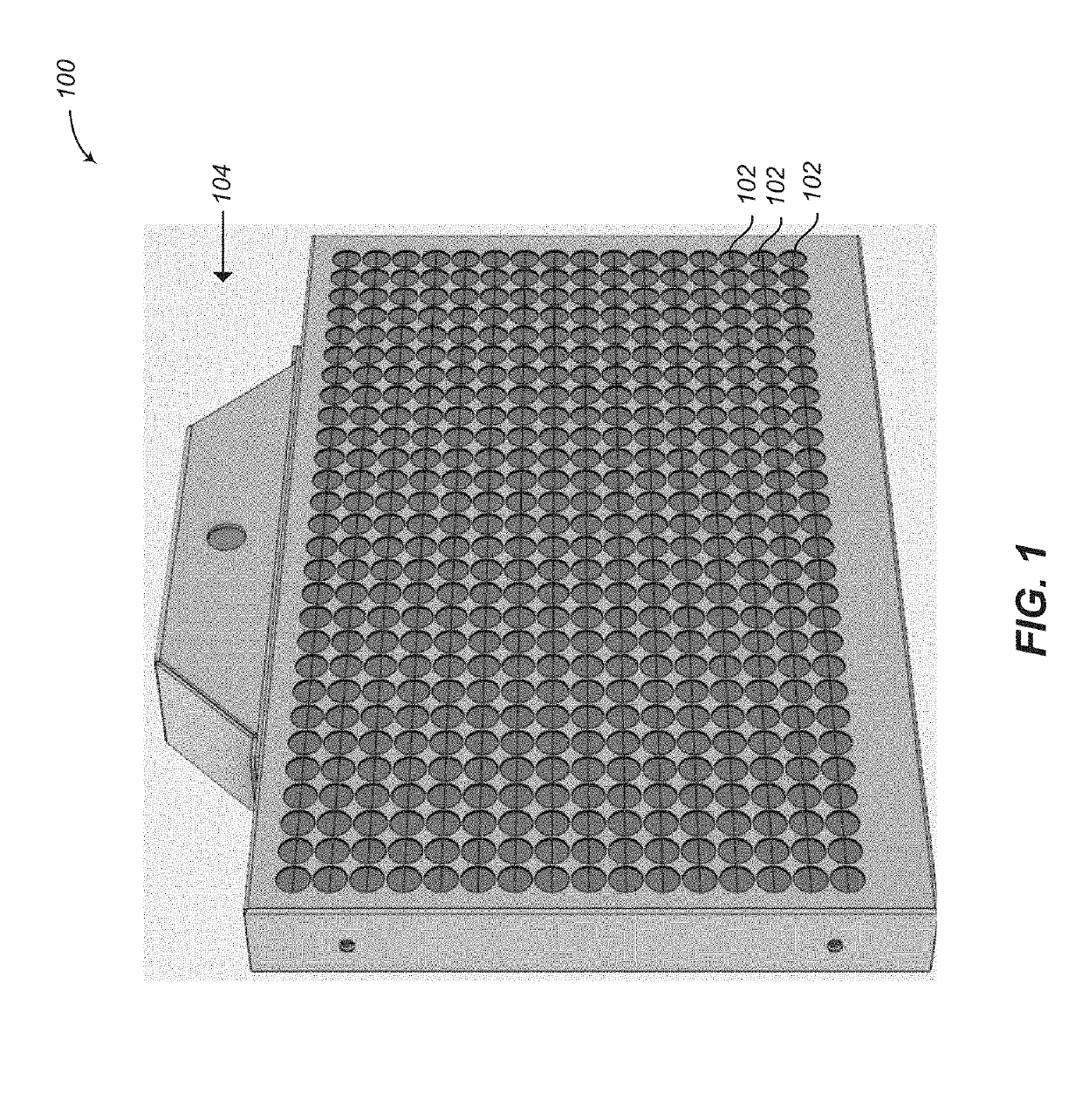
[0045]FIG. 1 is a front, perspective view of a precision MV display device 100 according to one or more embodiments of the present disclosure. The MV display device 100 includes a grid of multi-view pixels 102 and has a quadrilateral (e.g., rectangular) shape. Other shapes and configurations are within the scope of the present disclosure. To a viewer, the MV display device 100 resembles an ordinary light emitting diode (LED) display. In one or more embodiments, the MV display device 100 includes an integrated camera 104 disposed over the grid of multi-view pixels 102. The camera 104 is an example of a sensing system that is used to monitor activity in the field of view of the MV display device 100. In one or more embodiments, such a sensing system includes, or consists entirely of, sensors that are not integrated into the MV display device 100.

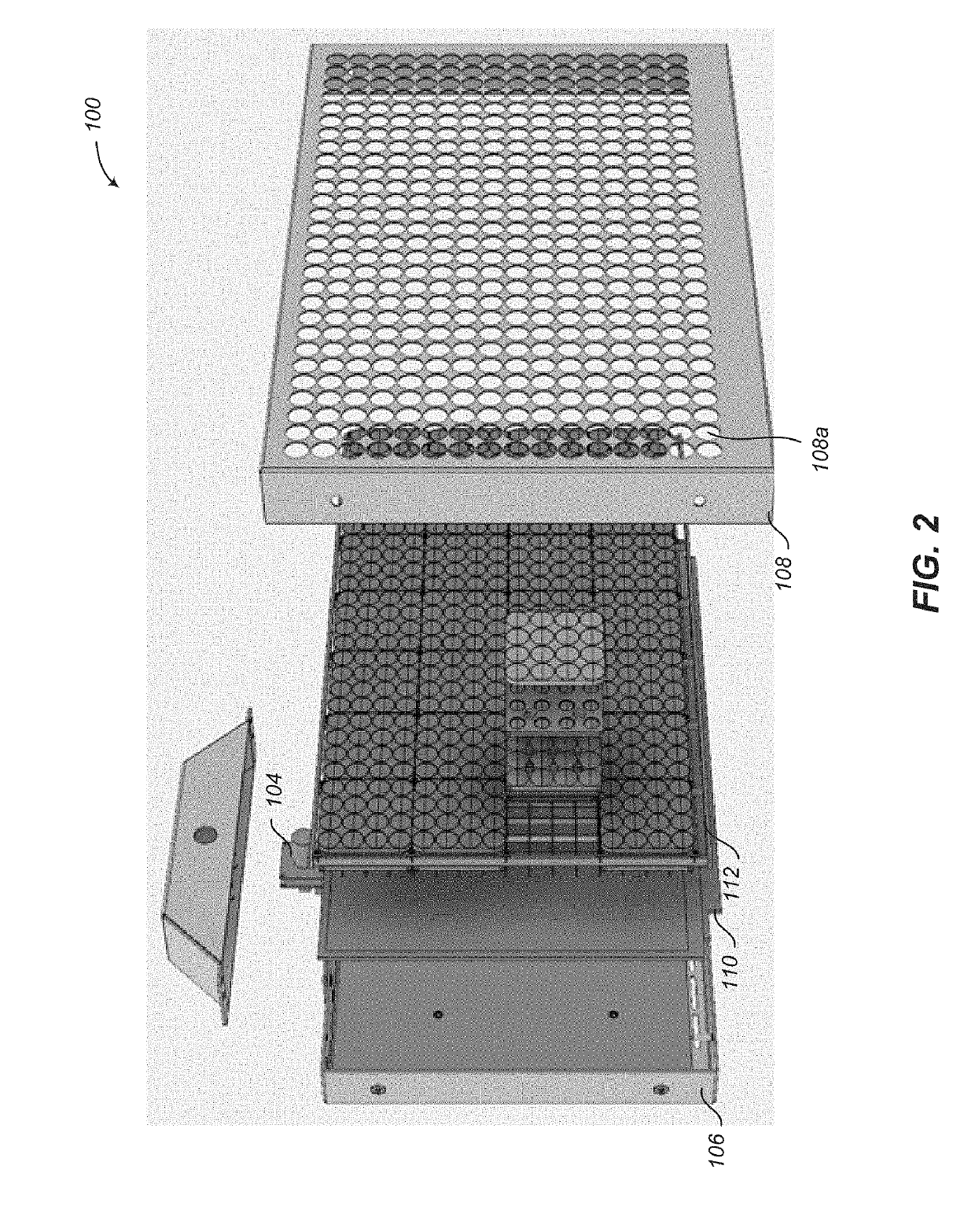
[0046]FIG. 2 is an exploded front view of a precision MV display device 100 according to one or more embodiments of the present disclosure. T...


PUM

PropertyMeasurementUnit
Transparencyaaaaaaaaaa
Contentaaaaaaaaaa
Timeaaaaaaaaaa

Abstract

A precision multi-view (MV) display system can accurately and simultaneously display different content to different viewers over a wide field of view. The MV display system may include features that enable individual MV display devices to be easily and efficiently tiled to form a larger MV display. A graphical interface enables a user to graphically specify viewing zones and associate content that will be visible in those zones in a simple manner. A calibration procedure enables the specification of content at precise viewing locations.

Description

BACKGROUNDTechnical Field[0001]The present disclosure relates to multi-view (MV) display systems, and more particularly, to extensible, precision MV display systems that can provide arbitrary (e.g., different) content to easily specified locations.Description of the Related Art[0002]The patent or application file contains at least one drawing executed in color. Copies of this patent or patent application publication with color drawing(s) will be provided by the Office upon request and payment of the necessary fee.[0003]A multi-view display simultaneously presents different content to different viewers based on the location of each viewer relative to the display. Novelty lenticular cards are a simple example of a multi-view system. When viewed from different angles they can reveal different images. They use a series of cylindrical lenslets placed over stripes of content to direct each content stripe in a unique angular range. A complete image is formed by having the stripes from a si...

Claims


Application Information

Patent Timeline
IPC IPC(8): H04N13/327G02B27/22G06F3/0484H04N13/398H04N13/305H04N13/324
CPCH04N13/305H04N13/398H04N13/324G02B27/2214G06F3/04847H04N2213/001H04N13/327H04N13/307G02B3/0031G02B2207/123G02B1/11H04N13/351G09F9/3026G09F19/14G02B30/27
Inventor NG, ALBERT HANDIETZ, PAUL HENRYDUNCAN, WILLIAM JERRYLATHROP, MATTHEW STEELETHOMPSON, DAVID STEVEN
Owner MISAPPLIED SCI INC
Learn More