Error compensation for sheathed sensors

a technology of error compensation and sheath, applied in the field of sensors, can solve the problems of leakage through the isolation resistance, the isolation resistance can change over time, and the separation connection is required to the protective sheath of the sensor, and achieve good and efficient effects

Active Publication Date: 2019-05-16
MELEXIS TECH NV
View PDF0 Cites 0 Cited by
  • Summary
  • Abstract
  • Description
  • Claims
  • Application Information

AI Technical Summary

Benefits of technology

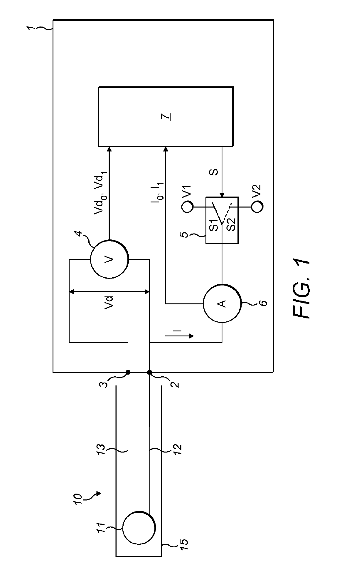
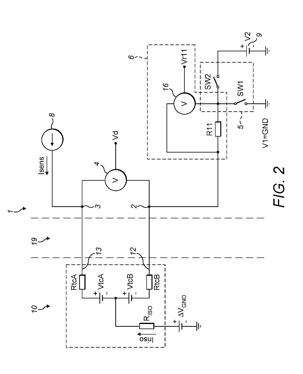
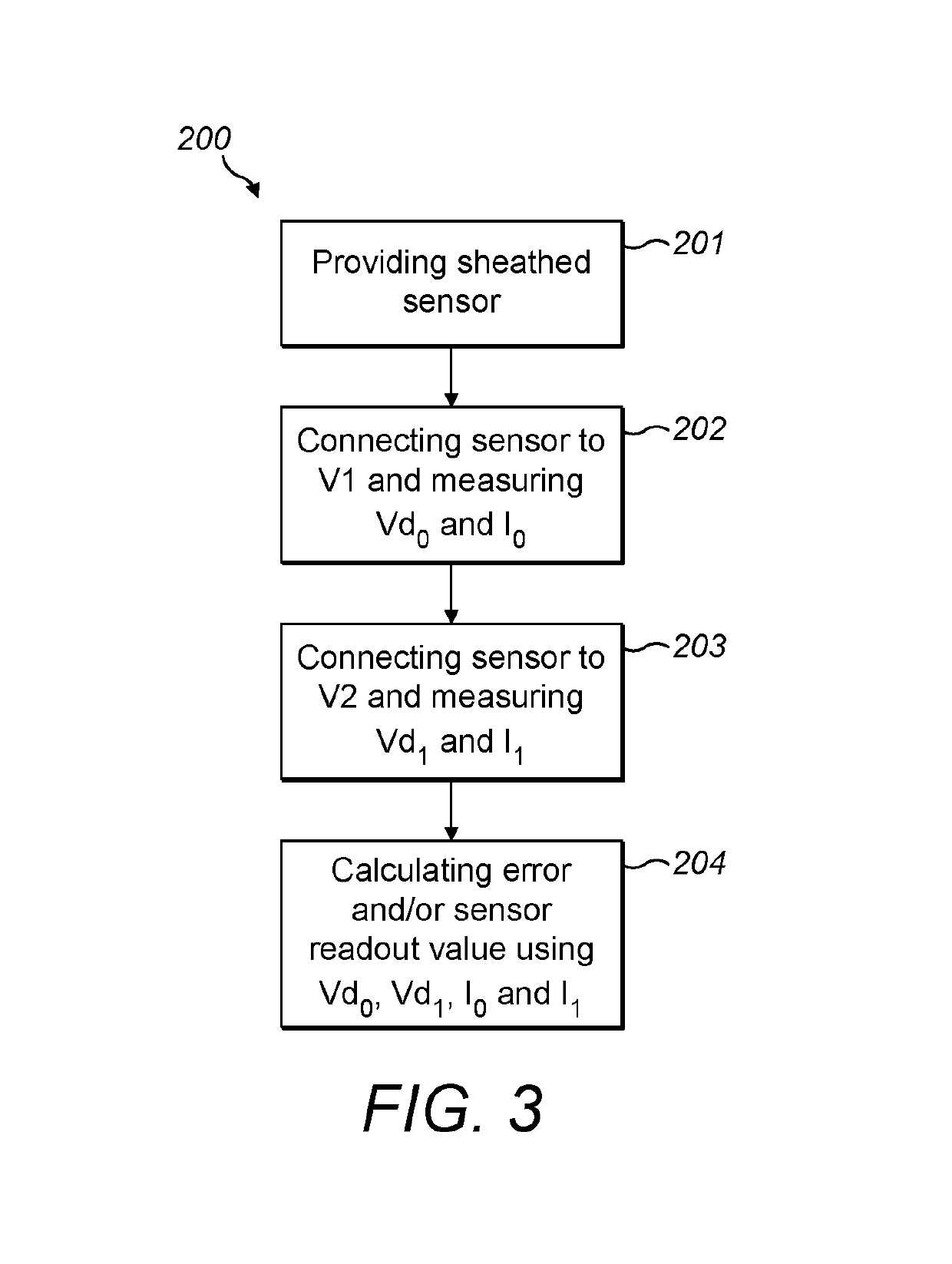
The present invention provides means and methods for accurately determining and compensating for measurement errors in sheathed sensors caused by leakage through insulation resistance and parasitic lead-to-ground voltage. This allows for the calculation and compensation of different types of errors without directly measuring insulation resistance. The invention also includes a sensor system comprising a circuit and a sheathed sensor with complementary terminals connected to a pair of sensor signal leads, which are positioned within the sheath to reduce external electromagnetic disturbances. The method involves measuring voltage and current differences over the sensor element and calculating an error value that is corrected for the measurement error by taking into account the voltage and current differences.

Problems solved by technology

However, such isolation resistance can change over time, for example due to various factors such as heating and vibrations.
Therefore, when the isolation resistance is too low, a leakage through the isolation resistance can occur.
This leakage can influence the sensor measurement, e.g. can lead to a measurement error.
However, it is a disadvantage of the disclosed approach that a separate connection is required to the protective sheath of the sensor.
Furthermore, while an approach in accordance with D1 may be used to take a resistance between a sensor terminal and the protective sheath into account, it does not compensate for a resistance between the protective sheath and the effective ground GND, e.g. for the difference ΔVGND.

Method used


Image

  • Error compensation for sheathed sensors
  • Error compensation for sheathed sensors
  • Error compensation for sheathed sensors

Examples


Embodiment Construction

[0033]The present invention will be described with respect to particular embodiments and with reference to certain drawings but the invention is not limited thereto but only by the claims. The drawings described are only schematic and are non-limiting. In the drawings, the size of some of the elements may be exaggerated and not drawn on scale for illustrative purposes. The dimensions and the relative dimensions do not correspond to actual reductions to practice of the invention.

[0034]Furthermore, the terms first, second and the like in the description and in the claims, are used for distinguishing between similar elements and not necessarily for describing a sequence, either temporally, spatially, in ranking or in any other manner. It is to be understood that the terms so used are interchangeable under appropriate circumstances and that the embodiments of the invention described herein are capable of operation in other sequences than described or illustrated herein.

[0035]Moreover, t...


PUM

PropertyMeasurementUnit
voltage measurementaaaaaaaaaa
voltageaaaaaaaaaa
reference voltageaaaaaaaaaa

Abstract

A circuit for determining and / or compensating for a measurement error of a sheathed sensor due to a property of a sheath of that sheathed sensor comprises a first and a second terminal for connecting to a pair of sensor signal leads of a sensor element in a sheathed sensor and a voltage measurement circuit. A switching unit controls switching an electrical connection between a first and a second state. A correction measurement circuit generates a correction signal indicative of that a measured current running from the first terminal through the switching unit. A controller receives the measurement and correction signal in both the first and second state, and calculates an error value indicative of the measurement error and / or a sensor readout value that is corrected for the measurement error by taking the measurement and correction signal into account as obtained in both the first and second state.

Description

FIELD OF THE INVENTION[0001]The invention relates to the field of sensors embedded in a protective sheath. More specifically it relates to a circuit and method for determining of and / or compensating for a measurement error of a sheathed sensor due to a property of a sheath of the sheathed sensor.BACKGROUND OF THE INVENTION[0002]Various sensors known in the art, such as thermocouples and resistive temperature detectors (RTD) elements, are sensitive to their external environment. For protection, such sensors require electrical isolation, for example by embedding the sensor in a sheath and filling the space between the sensor and the sheath with an electrically insulating material. The resistance between the sensor and its sheath is generally referred to as isolation resistance (RISO). However, such isolation resistance can change over time, for example due to various factors such as heating and vibrations.[0003]In applications, the sensor sheath can be at an electric potential that di...

Claims


Application Information

Patent Timeline
Patent Type & Authority Applications(United States)
IPC IPC(8): G01K7/10G01K7/02G01K1/08
CPCG01K7/10G01K7/021G01K1/08G01K15/005G01R27/08G01R31/2829
Inventor KASSOVSKI, VIKTORBOBCHEV, KOSTADINLESICHKOV, IVAN
Owner MELEXIS TECH NV
Why Eureka
Try Eureka