Device and method for establishing an artificial arterio-venous fistula

Active Publication Date: 2019-05-16
EDWARDS LIFESCIENCES CORP
View PDF0 Cites 5 Cited by
  • Summary
  • Abstract
  • Description
  • Claims
  • Application Information

AI Technical Summary

Benefits of technology

The patent is about using a coupler to join two blood vessels together. The coupler can be made of a material that is absorbed by the body over time, so it doesn't permanently stay in the patient's body. This can be beneficial because it helps to avoid changing the natural flow of blood in the patient. The coupler can also be placed at a location that expands after the fistula is created, which is when the patient's body increases the amount of blood flow through a newly created channel.

Problems solved by technology

In COPD, the lungs are damaged and the airways are partly obstructed, making it difficult to breath and leading to a gradual loss of lung function.
Symptoms of COPD include chronic cough, excessive sputum production, low blood oxygen levels and severe disabling shortness of breath.
These serious conditions affect many people, and the primary treatments are merely ameliorative.
In advanced cases of COPD, lung reduction surgery is sometimes performed, but it is not clear that it helps.
There is no known cure for COPD.

Method used


Image

  • Device and method for establishing an artificial arterio-venous fistula
  • Device and method for establishing an artificial arterio-venous fistula
  • Device and method for establishing an artificial arterio-venous fistula

Examples


Embodiment Construction

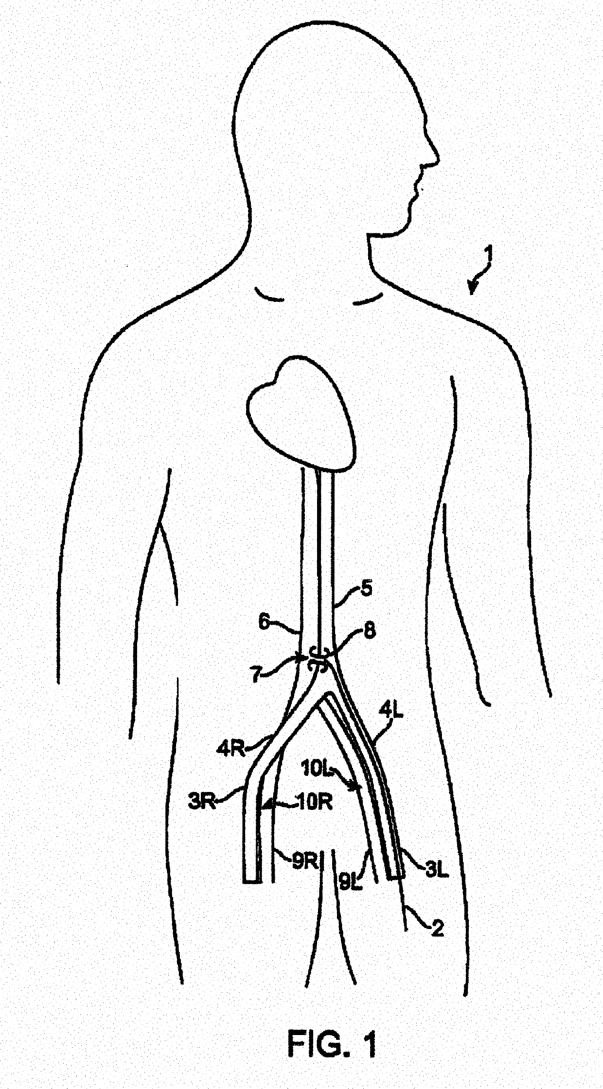
[0068]FIG. 1 illustrates the method of installing the shunt rivet to create and maintain an artificial aortocaval fistula. The patient 1 is shown with a delivery catheter 2 inserted into the left femoral artery / external femoral artery 3L and pushed upwardly through the left common iliac artery 4L to a point just above the aortic / iliac bifurcation in the distal abdominal aorta 5. The inferior vena cava 6 runs parallel to the aorta, and typically is contiguous with the aorta. As shown in the illustration, the left femoral artery provides a nearly straight pathway to a suitable site of the artificial aortocaval fistula 7 within the abdominal aorta (the right femoral vein 9R also provides a straight pathway to the same site on the vena cava side, and may be also be used as an access pathway). The fistula is created by forming a small hole or slit through the walls of both the aorta and the vena cava at immediately adjacent sites, and is maintained by inserting the shunt rivet 8 describe...


PUM


Abstract

A shunt rivet for implantation between a first body space and a second body space in a patient, such as to treat chronic obstructive pulmonary disease.

Description

CROSS-REFERENCE TO RELATED APPLICATIONS[0001]This application is a continuation of U.S. patent application Ser. No. 14 / 587,314, filed Dec. 31, 2014, which is a continuation of U.S. patent application Ser. No. 12 / 752,397, filed Apr. 1, 2010 (now U.S. Pat. No. 8,926,545 issued Jan. 6, 2015), which claims the benefit of priority to U.S. Provisional Application No. 61 / 170,774, filed Apr. 20, 2009, and which is also a continuation-in-part of U.S. patent application Ser. No. 11 / 696,635 filed Apr. 4, 2007 (now U.S. Pat. No. 7,828,814 issued Nov. 9, 2010), which is a continuation-in-part of U.S. patent application Ser. No. 11 / 356,876, filed Feb. 17, 2006 (now U.S. Pat. No. 9,706,997 issued Jul. 18, 2017), which is a continuation-in-part of U.S. patent application Ser. No. 10 / 927,704 filed Aug. 27, 2004 (now abandoned), the contents of each of which is incorporated herein by reference in their entirety for all purposes.FIELD OF THE INVENTION[0002]The inventions described below relate to trea...

Claims


Application Information

Patent Timeline
IPC IPC(8): A61M1/00A61B17/10A61B17/11A61B17/08
CPCA61M1/0094A61B17/10A61B17/11A61B17/083A61B2017/1107A61B2017/1139A61B2017/00004A61B2017/00867A61M1/88
Inventor BRENNEMAN, RODNEY A.FLAHERTY, J. CHRISTOPHERKELLERMAN, BRAD
Owner EDWARDS LIFESCIENCES CORP
Why Eureka
Try Eureka