Bi-directional coupler
a bi-directional coupler and coupler technology, applied in the direction of coupling devices, multiple-port networks, electrical devices, etc., can solve the problem of requiring much effort in circuit design, and achieve the effect of easy bi-directionality
- Summary
- Abstract
- Description
- Claims
- Application Information
AI Technical Summary
Benefits of technology
Problems solved by technology
Method used
Image

Examples
first embodiment
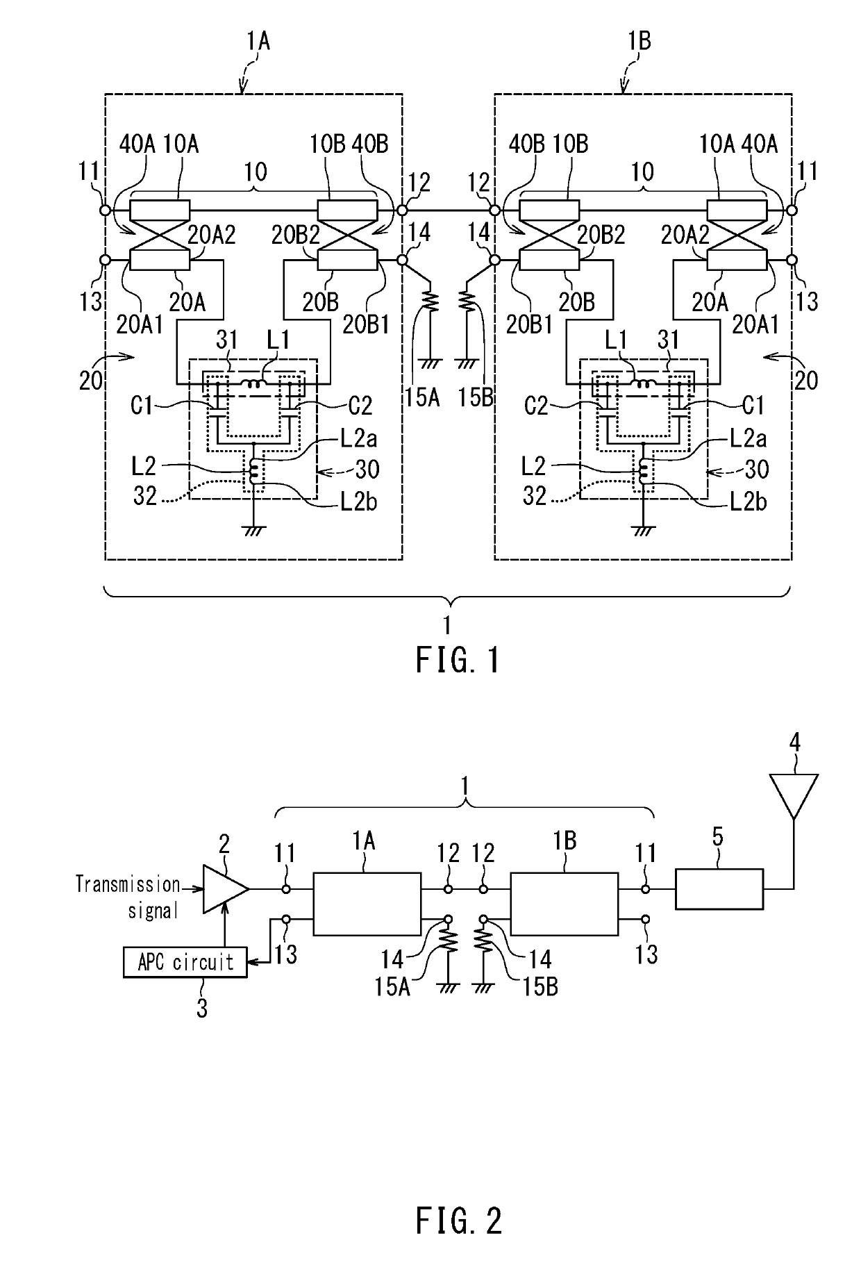
[0039]Preferred embodiments of the present invention will now be described in detail with reference to the drawings. First, reference is made to FIG. 1 to describe the circuit configuration of a bi-directional coupler according to a first embodiment of the invention.
[0040]As shown in FIG. 1, the bi-directional coupler 1 according to the first embodiment includes a first individual directional coupler 1A and a second individual directional coupler 1B. The first and second individual directional couples 1A and 1B are individual electronic components having mutually equivalent circuit configurations. Each of the first and second individual directional couplers 1A and 1B includes a first terminal 11, a second terminal 12, a third terminal 13, a fourth terminal 14, a main line 10 connecting the first terminal 11 and the second terminal 12, and a subline 20 connecting the third terminal 13 and the fourth terminal 14.
[0041]The subline 20 includes at least one coupling line section configur...
second embodiment
[0115]A bi-directional coupler 1 according to a second embodiment of the invention will now be described. FIG. 15 is a circuit diagram illustrating the circuit configuration of the bi-directional coupler 1 according to the second embodiment. The bi-directional coupler 1 according to the second embodiment includes neither of the first and second resistors 15A and 15B of the first embodiment, but includes a delay line 16 that electrically connects the fourth terminal 14 of the first individual directional coupler 1A and the fourth terminal 14 of the second individual directional coupler 1B. The delay line 16 causes a change in the phase of a signal passing therethrough. The magnitude of the change in the phase caused by the delay line 16 is more than 0° and 360° or less for a signal of a frequency within the service frequency band of the bi-directional coupler 1.
[0116]The bi-directional coupler 1 according to the present embodiment operates differently from the bi-directional coupler ...
third embodiment
[0128]A bi-directional coupler 1 according to a third embodiment of the invention will now be described. FIG. 18 is a circuit diagram illustrating the circuit configuration of the bi-directional coupler 1 according to the third embodiment. The bi-directional coupler 1 according to the third embodiment includes none of the first and second resistors 15A and 15B of the first embodiment and the delay line 16 of the second embodiment. In the bi-directional coupler 1 according to the third embodiment, the fourth terminal 14 of the second individual directional coupler 1B is electrically connected to the fourth terminal 14 of the first individual directional coupler 1A without the delay line 16 therebetween.
[0129]In the present embodiment, the fourth terminal 14 of the second individual directional coupler 1B may be physically directly connected to the fourth terminal 14 of the first individual directional coupler 1A, or may be electrically connected thereto via a short line that hardly c...
PUM
 Abstract
Description
Claims
Application Information
 - R&D
- Intellectual Property
- Life Sciences
- Materials
- Tech Scout
- Unparalleled Data Quality
- Higher Quality Content
- 60% Fewer Hallucinations
Browse by: Latest US Patents, China's latest patents, Technical Efficacy Thesaurus, Application Domain, Technology Topic, Popular Technical Reports.
© 2025 PatSnap. All rights reserved.Legal|Privacy policy|Modern Slavery Act Transparency Statement|Sitemap|About US| Contact US: help@patsnap.com