
Image processing apparatus, image processing method, and program

a technology of image processing and image quality, applied in the field of image processing apparatus, image processing method, and program, can solve the problems of image quality degradation, display device capable of displaying hdr images, loss of luminance information and color information inherent in hdr images, etc., and achieve high luminance region, high luminance, and high quality sdr images without significant reduction in image average luminance

Active Publication Date: 2019-05-09
SONY CORP
View PDF7 Cites 9 Cited by
  • Summary
  • Abstract
  • Description
  • Claims
  • Application Information

AI Technical Summary

Benefits of technology

The present invention is about a method and apparatus for generating a high quality SDR image without reducing the average luminance of the image. This is done through a matrix conversion process for an HDR image. By applying a specific conversion matrix to low luminance region pixels, the apparatus can generate a high quality SDR image with improved image quality. This method and apparatus can have various applications, such as in video production or display technology.

Problems solved by technology

On the one hand, a content creation side actively captures and produces the HDR images, on the other hand, many of display devices such as televisions at home to view content are not display devices capable of displaying the HDR images under existing circumstances.
When an HDR image is input and displayed on the SDR display device, luminance information and color information inherent to the HDR image are lost, and an image with degraded image quality is displayed.
However, not all of display devices have the display mapping function.
Further, there is a concern that, when dynamic range conversion is simply performed by linear scaling, a large amount of information is lost and the HDR image becomes an image with visual appearance that is greatly different before and after the conversion.
Such a loss of information is contrary to the intention of the producer and supplier of the content.

Method used


Image

  • Image processing apparatus, image processing method, and program
  • Image processing apparatus, image processing method, and program
  • Image processing apparatus, image processing method, and program

Examples


Embodiment Construction

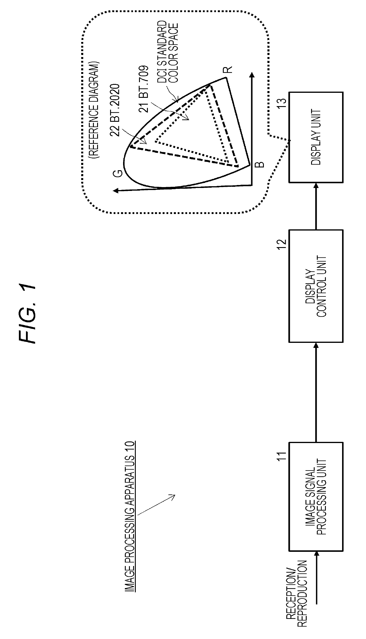
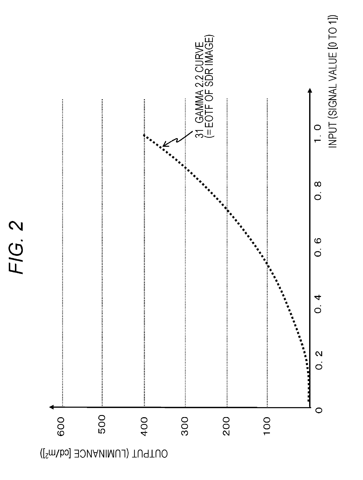
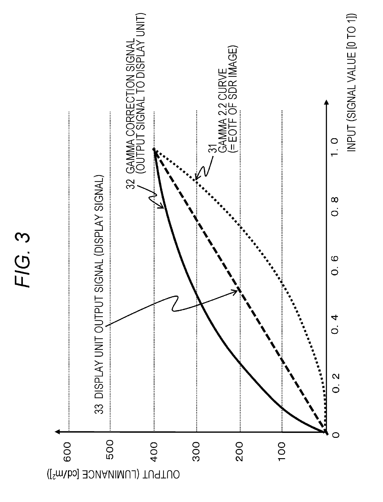
[0067]Hereinafter, an image processing apparatus, an image processing method, and a program of the present disclosure will be described in detail with reference to the drawings. Note that the description will be given according to the following items.

[0068]1. Outline of Image Display Processing in Image Processing Apparatus

[0069]2. Problems in HDR Image Output Processing for SDR Display Unit

[0070]3. Hybrid Log-Gamma HDR Image

[0071]4. Configuration to Execute Conversion from HDR Image into SDR Image, Applying Matrix Conversion

[0072]5. Matrix Conversion Processing Configuration In Which Deterioration of Luminance Level of SDR Image After Conversion is Prevented

[0073]6. Configuration Example of Image Processing Apparatus

[0074]7. Conclusion of Configurations of Present Disclosure

[0075][1. Outline of Image Display Processing in Image Processing Apparatus]

[0076]First, a typical processing example of image display processing in an image processing apparatus will be described with reference...


PUM


Abstract

Provided are an apparatus and a method for generating a high quality SDR image without significant reduction in image average luminance by matrix conversion for an HDR image. An image signal processing unit that converts the HDR image into the SDR image converts a pixel value of the HDR image into a pixel value of the SDR image, applying one conversion matrix to low luminance region pixels having luminance that is a prescribed threshold or less among constituent pixels of the HDR image. A high luminance region pixel having higher luminance than the prescribed threshold is set as a highest output pixel of the SDR image after conversion. The conversion matrix to be applied is a matrix having setting in which a change rate of a memory color set in a Macbeth color chart becomes smaller.

Description

TECHNICAL FIELD[0001]The present disclosure relates to an image processing apparatus, an image processing method, and a program. More specifically, the present disclosure relates to an image processing apparatus, an image processing method, and a program for making a high dynamic range (HDR) image displayable on a standard dynamic range (SDR) display device that is a normal dynamic range image display device widely used at present without greatly deteriorating the image quality.BACKGROUND ART[0002]Recently, the dynamic range of images has been increased due to an increase in the number of bits of imaging devices (image sensors), for example.[0003]The dynamic range of images can be generally expressed by a ratio of minimum luminance to maximum luminance.[0004]In a high dynamic range (HDR) image known as a high image quality image, the contrast ratio between maximum lightness color and lowest lightness color reaches, for example, 10000:1 or more, and the real world can be realisticall...

Claims


Application Information

Patent Timeline
Patent Type & Authority Applications(United States)
IPC IPC(8): G06T5/00G09G5/02G09G5/391H04N1/407H04N5/20H04N7/01
CPCG06T5/007G09G5/02G09G5/391H04N1/407H04N5/20H04N7/01H04N1/3871G09G5/10G09G2340/06G09G2320/0673G06T2207/20208G06T5/92H04N23/82G06T5/00H04N5/202G09G5/00G06T5/90
Inventor ETO, HIROAKI
Owner SONY CORP
Learn More