
Method for transmitting uplink control channel in wireless communication system and apparatus for same

a wireless communication system and control channel technology, applied in the field of wireless communication systems, can solve problems such as resource shortfall, and achieve the effect of optimizing and efficiently using the transmission of the uplink control channel

Active Publication Date: 2019-05-02
LG ELECTRONICS INC
View PDF0 Cites 10 Cited by
  • Summary
  • Abstract
  • Description
  • Claims
  • Application Information

AI Technical Summary

Benefits of technology

This patent is about a method for improving the efficiency of transmitting control channels in a wireless network. The base station can allocate resource elements for each user's control channel, making it more efficient. Users with low coverage can also benefit from this method, as the control channel is spread out over multiple symbols. Additionally, when multiple users are present, the amount of data transmitted can be increased by reducing the ratio of resource elements allocated to the control channel region. Overall, this method helps optimize network performance and allows for more efficient control channel transmission.

Problems solved by technology

Today, the shortage of resources is caused due to an explosive increase of traffic, and more advanced mobile communication systems are required due to user's need for higher speed services.

Method used


Image

  • Method for transmitting uplink control channel in wireless communication system and apparatus for same
  • Method for transmitting uplink control channel in wireless communication system and apparatus for same
  • Method for transmitting uplink control channel in wireless communication system and apparatus for same

Examples


first embodiment

hannel Region of 1 Symbol Unit

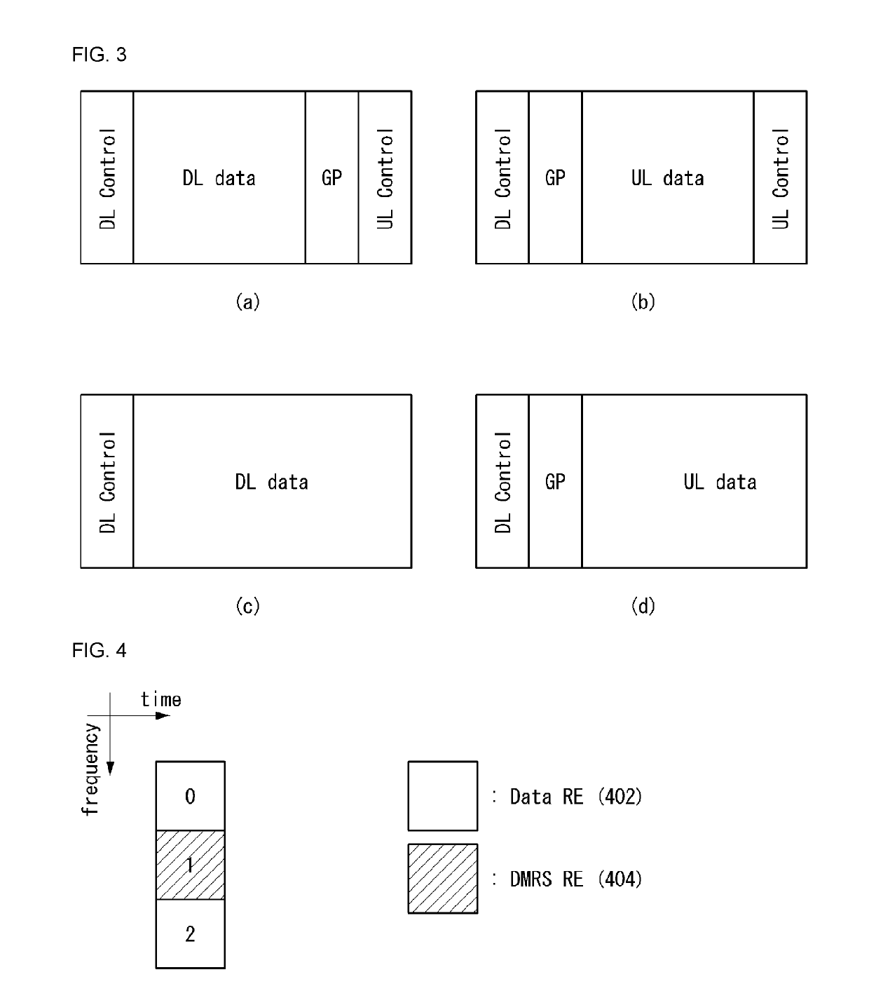
[0174]As described above, if an uplink control channel is configured in 1 symbol unit, in order for a UE to map uplink information to the uplink control channel, a resource element group (REG) including resource elements (REs) of a repeatable minimum unit may be considered. In other words, an REG may be considered as a basic unit for enabling a UE to transmit uplink control information.

[0175]In this case, the REG may be configured in various ways based on a type (or kind), number and / or assignment method of an RE.

[0176]FIG. 4 illustrates an example of a resource element group (REG) to which a method proposed in this specification may be applied. FIG. 4 is for only convenience of description and does not limit the scope of the present invention.

[0177]Referring to FIG. 4, the REG may include three REs. Two of the three REs may include data REs 402, and the remaining one may include a DMRS RE 404. That is, if an REG includes three REs, uplink control infor...

second embodiment

annel Region of Plurality of Symbol Units

[0224]However, the structure of an uplink control channel region of 1 symbol unit (first embodiment), such as that described above, includes a small number of symbols, but may have a disadvantageous characteristic with respect to a UE having low coverage due to insufficient energy. Accordingly, a structure in which an uplink control channel is configured in a plurality of symbols for UEs having low coverage needs to be considered. For example, a structure in which an uplink control channel is subjected to frequency division multiplexing (FDM) along with an uplink data channel may be considered. For convenience of description, the following methods have been illustrated as being applied to a structure in which an uplink control channel and an uplink data channel are subjected to FDM, but may be applied to a case where an uplink control channel is configured in several symbols as a TDM structure not the FDM structure.

[0225]An uplink control cha...


PUM


Abstract

Disclosed are a method for transmitting an uplink control channel in a wireless communication system and an apparatus for the same. Particularly, the method comprises the steps of: receiving allocation of a resource region including one or more symbols for transmission of an uplink control channel; and mapping uplink control information and a reference signal to each specific resource group unit in the allocated resource region, wherein the specific resource group unit may comprise a first resource element having the reference signal mapped thereto and second resource elements having the at least one piece of uplink control information mapped thereto, the second resource elements may be arranged adjacent to the first resource element, and the second resource elements may be multiplexed according to orthogonal cover codes in a clockwise or counter-clockwise direction.

Description

TECHNICAL FIELD[0001]The present invention relates to a wireless communication system and, more particularly, to a method for transmitting an uplink control channel and an apparatus supporting the same.BACKGROUND ART[0002]Mobile communication systems have been developed to provide voice services while ensuring the activity of a user. However, the mobile communication systems have been expanded to their regions up to data services as well as voice. Today, the shortage of resources is caused due to an explosive increase of traffic, and more advanced mobile communication systems are required due to user's need for higher speed services.[0003]Requirements for a next-generation mobile communication system basically include the acceptance of explosive data traffic, a significant increase of a transfer rate per user, the acceptance of the number of significantly increased connection devices, very low end-to-end latency, and high energy efficiency. To this end, research is carried out on va...

Claims


Application Information

Patent Timeline
Patent Type & Authority Applications(United States)
IPC IPC(8): H04L5/00
CPCH04L5/0048H04L5/0092H04L5/0094H04L5/0053H04L5/0051H04L5/0007H04L27/2602H04L27/26035H04L5/00H04W72/23
Inventor KWAK, KYUHWANYANG, SUCKCHELKIM, SEONWOOKYI, YUNJUNGHWANG, DAESUNG
Owner LG ELECTRONICS INC
Learn More