
Concentrated high-speed rigid hub

a hub and high-speed technology, applied in the direction of bearing unit rigid support, couplings, agricultural machines, etc., can solve the problems of reducing the service life of the standard hub, so as to increase the structural strength, increase the service life, and maximize the strength of the attachment point

Active Publication Date: 2019-04-25
PRESCRIPTION TILLAGE TECH
View PDF0 Cites 2 Cited by
  • Summary
  • Abstract
  • Description
  • Claims
  • Application Information

AI Technical Summary

Benefits of technology

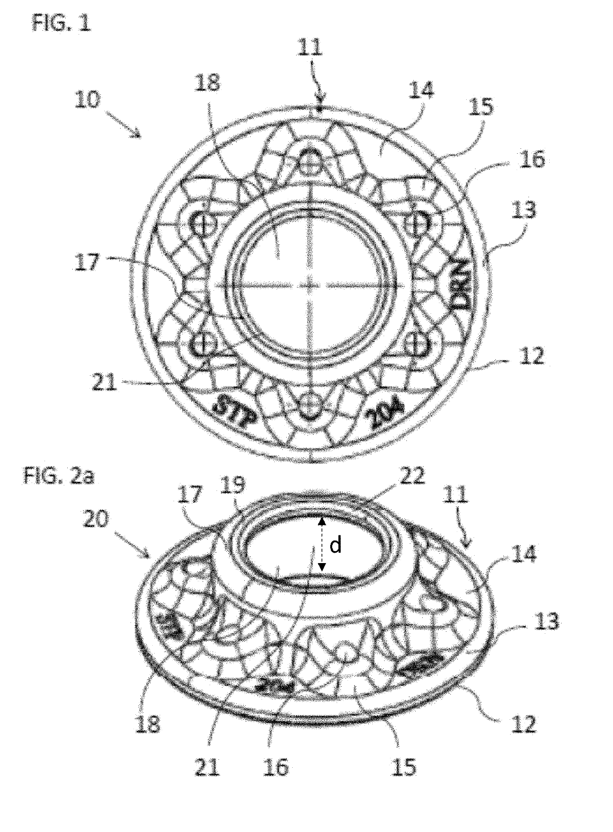
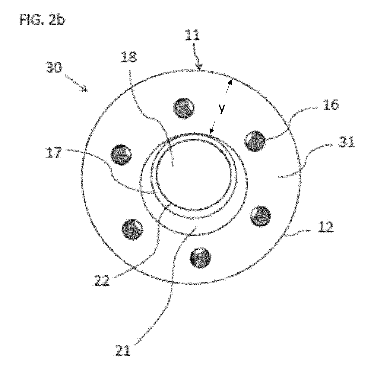
The present invention provides a concentrated high-speed rigid hub for heavier planters, planting and seeding devices in multiple applications. The hub is made of high strength forging steel and medium carbon cast steel, with increased structural strength and maximized attachment points. Increased contact area interface prevents stress loads on components, resulting in optimal absorption of forces throughout the blade-hub-bearing assembly and prevention of wobbling and breakage. The hub is less prone to loosening and capable of handling flex forces and stress with repeated use, saving agricultural professionals thousands of dollars in parts, replacement labor, and downtime. The hub further comprises a narrow circulative side wall and a hub top wall with rigid, heavy duty deep bosses or gussets adapted for receiving bolts, which maximizes the strength of attachment points. The hub provides a maximum blade and bearing contact area, in a concentrated size, configured for maximum soil depth.

Problems solved by technology

Accordingly, traditional hubs do not allow for heavy planters, high-speed planting and seeding devices in multiple and multiple challenging applications such as no-till, moist Bt stubble, high concentrations of stubble, high CEC soils, compact soils, cover and green crops with massive structured root systems, new heavy down pressure systems actuated hydraulically or by air.
As a result, standard hubs lack longevity and must be replaced after minimum use.
It also results in downtime that creates operational losses.
This oftentimes creates bearing flex, blade flex, blade out of round, blade wobble [common in the industry with pressed steel hubs that are press riveted] and paired blades contact or friction, which contribute to premature blade failure.
Current hubs do not generally provide for absorption of forces and stability and therefore agricultural implements, i.e., coulter blades, for example, are subject to breaking.
Additionally, currently utilized bearings utilized in hub to Bearing outer race contact fails to provide maximum contact at the bearing—hub to interface, and therefore bearings and Hubs are prone to loosening.
This loosening causes wobbling of assembly at stress points, including the bearing—hub loads and bearing—hub to blade loads, causing breakage of the blade (twisting redirecting forces), breakage of bearings, and / or breakage of the hub.
As the hub loosens on the bearing and allows the blade to start wobbling, even at 0.025 inch increments, there is an increase in pressure on the bearing causing flexing translating to damage to the bearing, blade and / or hub.
Typically, agricultural professionals cannot simply replace a damaged bearing and / or hub because of wear patterns making it difficult for proper compression contact with the replacement hub and / or bearing, resulting in loosing and or wobbling during use, and ultimately breakage again.
Consequently, when damage results generally a whole new blade, hub and bearing assembly must be purchased to replace the damaged assembly.
These problems in the art concerning hub to bearing to blade assemblies in the agricultural field currently result in the need for roughly two dozen sets of blade—roller bearing—hub assembly replacements for the life of the agricultural machinery, such as planters.
Blade assembly costs compounded by labor and lost operating time cost agricultural professionals thousands of dollars.

Method used


Image

  • Concentrated high-speed rigid hub
  • Concentrated high-speed rigid hub
  • Concentrated high-speed rigid hub

Examples


Embodiment Construction

[0030]Reference will now be made in detail to the presently preferred embodiments of the invention, examples of which are illustrated in the accompanying drawings. The subject coulter blade hub or Concentrated High-Speed Rigid Hub (CHRH) shall be referred to throughout as the CHRH, or the subject coulter blade hub.

[0031]The following description presents certain specific embodiments of the present invention. However, the present invention may be embodied in a multitude of different ways, as defined by the subjoined claims. In this description, reference is made to the drawings wherein like parts are designated with like numerals throughout.

[0032]The subject CHRH provides a rigid, heavy-duty hub having deep bosses or gussets, maximum blade and bearing outer race contact area, in a concentrated size, configured for maximum seeding depth without depth wheel or arm contact. The subject hub also lessens or stops bearing flex, blade flex, Blade out of Round, Blade wobble [which is common ...


PUM


Abstract

A concentrated high-speed rigid hub allows for heavier planters, high-speed planting and seeding devices in multiple and multiple challenging applications such as No-Till, High CEC soils, Compact Soils, Moist soils, High concentrations of Stubble and or Bt crops, and Cover or Green crops with massive structured root systems. The hub is made of one of high strength forging steel and medium carbon cast steel, whereby the hub lessons hub flexing, hub bending, cracking and premature failure. The hub comprises rigid, heavy duty deep bosses or gussets which increase structural strength and maximize the strength of attachment points adapted for either bolts or rivets attachment to a blade or object.

Description

[0001]This application claims the benefit of U.S. Provision Application No. 62 / 574,365 filed October 19, 2017, the subject matter of which is hereby incorporation in its entirety by reference thereto.FIELD OF THE INVENTION[0002]The present invention relates generally to agriculture tillage equipment; more particularly, to a hub and hub assembly especially for use with a coulter blade.DESCRIPTION OF THE PRIOR ART[0003]Traditional agriculture requires turning of the soil to effectively bury desirable stubble and create needed composted material. With the advent of reduced tillage and minimum tillage farming techniques, coulter blades may be used to increase surface area by cutting and reducing the stubble to a manageable condition, thereby enabling compost and reuse of the desirable stubble.[0004]Mounting of coulter blades on tillage equipment is typically accomplished through hub assemblies. Standard hubs are made of pressed steel or cast, which were designed for full-till operations...

Claims


Application Information

Patent Timeline
IPC IPC(8): F16D1/076A01B71/04A01B15/18A01B23/06F16C19/18F16C33/32F16C33/38
CPCF16D1/076A01B71/04A01B15/18A01B23/06F16C19/18F16C33/32F16C33/3887F16C2310/00F16C2300/22F16C2300/32F16D2200/0021F16C35/06F16C19/54
Inventor CHRISTIE, RICHARD L.CHRISTIE, RYAN J.K.NANCE, JOHN D.
Owner PRESCRIPTION TILLAGE TECH
Learn More