
Guide vane having a connecting tube

a technology of connecting tube and guide tube, which is applied in the direction of blade accessories, machines/engines, stators, etc., can solve the problems of reducing the cooling power available for the retaining ring, affecting the operation of the retaining ring, and limiting the magnitude of the inlet temperatur

Active Publication Date: 2019-04-25
SIEMENS ENERGY GLOBAL GMBH & CO KG
View PDF6 Cites 0 Cited by
  • Summary
  • Abstract
  • Description
  • Claims
  • Application Information

AI Technical Summary

Benefits of technology

The present invention aims to provide a guide vane that helps position the connecting tube easily and reliably in a cost-effective manner.

Problems solved by technology

However, limits are set on the magnitude of the inlet temperature, inter alia by the thermal loadability of the components arranged in the flow duct.
However, this cooling fluid has already received heat in the airfoil of the guide vane, which reduces the cooling power available for the retaining ring.
However, it has been shown that these positioning means can be inadequate in order to ensure a sufficiently reliable positioning of the connecting tube in the cooling fluid inlet opening with regard to strong operationally induced vibrations of the turbomachine and thermal changes in length of the connecting tube.

Method used


Image

  • Guide vane having a connecting tube
  • Guide vane having a connecting tube
  • Guide vane having a connecting tube

Examples


Embodiment Construction

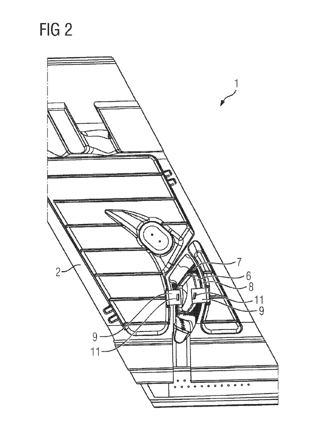
[0034]FIGS. 1 to 3 show a guide vane 1 for a turbomachine (not shown), in particular a gas turbine, according to an embodiment of the present invention. The guide vane 1 has an outer platform 2 which, in the properly mounted state of the guide vane 1, is arranged radially to the outside. Furthermore, the guide vane 1 comprises an airfoil 3 which extends in a longitudinal direction L and projects from the outer platform 2. A cavity 4 is defined in the interior of the airfoil 3. In addition, the guide vane 1 has an inner platform 5 which is arranged opposite to the outer platform 2 and is connected to the airfoil 3.

[0035]Moreover, the guide vane 1 comprises a connecting tube 6 which passes through the cavity 4 of the airfoil 3 in the longitudinal direction L. A first free end of the connecting tube 6 is connected to the inner platform 5 in an integrally bonded manner by welding and so as to be fluid-tight. The second free end of the connecting tube 6 is arranged in a cooling fluid inl...


PUM


Abstract

A guide vane for a turbomachine having an outer platform, a blade airfoil protruding from the outer platform, extending in a longitudinal direction and defining a cavity in its interior, an inner platform arranged opposite the outer platform and connected to the blade airfoil, and a connecting tube which passes through the cavity of the blade airfoil in the longitudinal direction. The first free end of the tube is inserted into a through-opening formed in the inner platform and materially bonded to the inner platform, and the second free end of the tube is arranged in a cooling fluid inlet opening formed on the outer platform, away from the edge thereof, and projecting outward from the outer platform. At least one guide is attached to the outer platform and designed to guide the connecting tube in the longitudinal direction in the event of a thermal change in length.

Description

CROSS REFERENCE TO RELATED APPLICATIONS[0001]This application is the US National Stage of International Application No. PCT / EP2017 / 058628 filed Apr. 11, 2017, and claims the benefit thereof. The International Application claims the benefit of European Application No. EP16166430 filed Apr. 21, 2016. All of the applications are incorporated by reference herein in their entirety.FIELD OF INVENTION[0002]The invention relates to a guide vane for a turbomachine, in particular a gas turbine, having, in the properly mounted state, an outer platform, an airfoil which projects from the outer platform, extends in a longitudinal direction and defines a cavity in its interior, an inner platform which is arranged opposite to the outer platform and is connected to the airfoil, and a connecting tube which passes through the cavity of the airfoil in the longitudinal direction, the first free end of which tube is inserted into a through-opening formed in the inner platform and connected to the inner ...

Claims


Application Information

Patent Timeline
IPC IPC(8): F01D5/18
CPCF01D5/188F01D9/065F05D2230/237F05D2230/232F01D5/189
Inventor AHMAD, FATHIRADULOVIC, RADAN
Owner SIEMENS ENERGY GLOBAL GMBH & CO KG
Learn More