
A method for selective etching of nanostructures

a nanostructure and selective etching technology, applied in the manufacture of microstructured devices, electrical apparatus, semiconductor devices, etc., can solve the problems of limited spatial resolution of ultraviolet lithography, difficult to achieve the fabrication of structures with lateral size below 20 nm with present processes, and limited uvl, which is commonly used for manufacturing semiconductor devices in industry, so as to reduce the number of steps needed in processing and reduce the production cost of final devices. , the effect of precise and efficient way

Active Publication Date: 2019-03-14
ALIXLABS AB
View PDF2 Cites 0 Cited by
  • Summary
  • Abstract
  • Description
  • Claims
  • Application Information

AI Technical Summary

Benefits of technology

The present invention provides a method for manufacturing nanostructures with high selectivity and without the need for lithography or multiple patterning. This method uses a dry etching process that uses low energy particles to remove material in a controlled way. The method can be used to fabricate nanostructures with lateral sizes below 20 nm and can be implemented in existing semiconductor fabrication plants without significant additional equipment or costs. The method also allows for gentle and damage-free processing of semiconductor devices and provides a more efficient and economical way for scaling down the device size. After the etch process, an annealing step can be used to reduce defects and improve the structure quality. Overall, this method provides a cost-effective and efficient way for manufacturing nanostructures with high precision and efficiency.

Problems solved by technology

However, fabrication of structures with lateral size below 20 nm is hard to achieve with present processes.
For instance, the spatial resolution of ultraviolet lithography, UVL, which is commonly used for manufacturing semiconductor devices in industry, is limited.

Method used


Image

  • A method for selective etching of nanostructures
  • A method for selective etching of nanostructures
  • A method for selective etching of nanostructures

Examples


Embodiment Construction

[0059]The present invention will now be described more fully hereinafter with reference to the accompanying drawings, in which currently preferred embodiments of the invention are shown. This invention may, however, be embodied in many different forms and should not be construed as limited to the embodiments set forth herein; rather, these embodiments are provided for thoroughness and completeness, and to fully convey the scope of the invention to the skilled person.

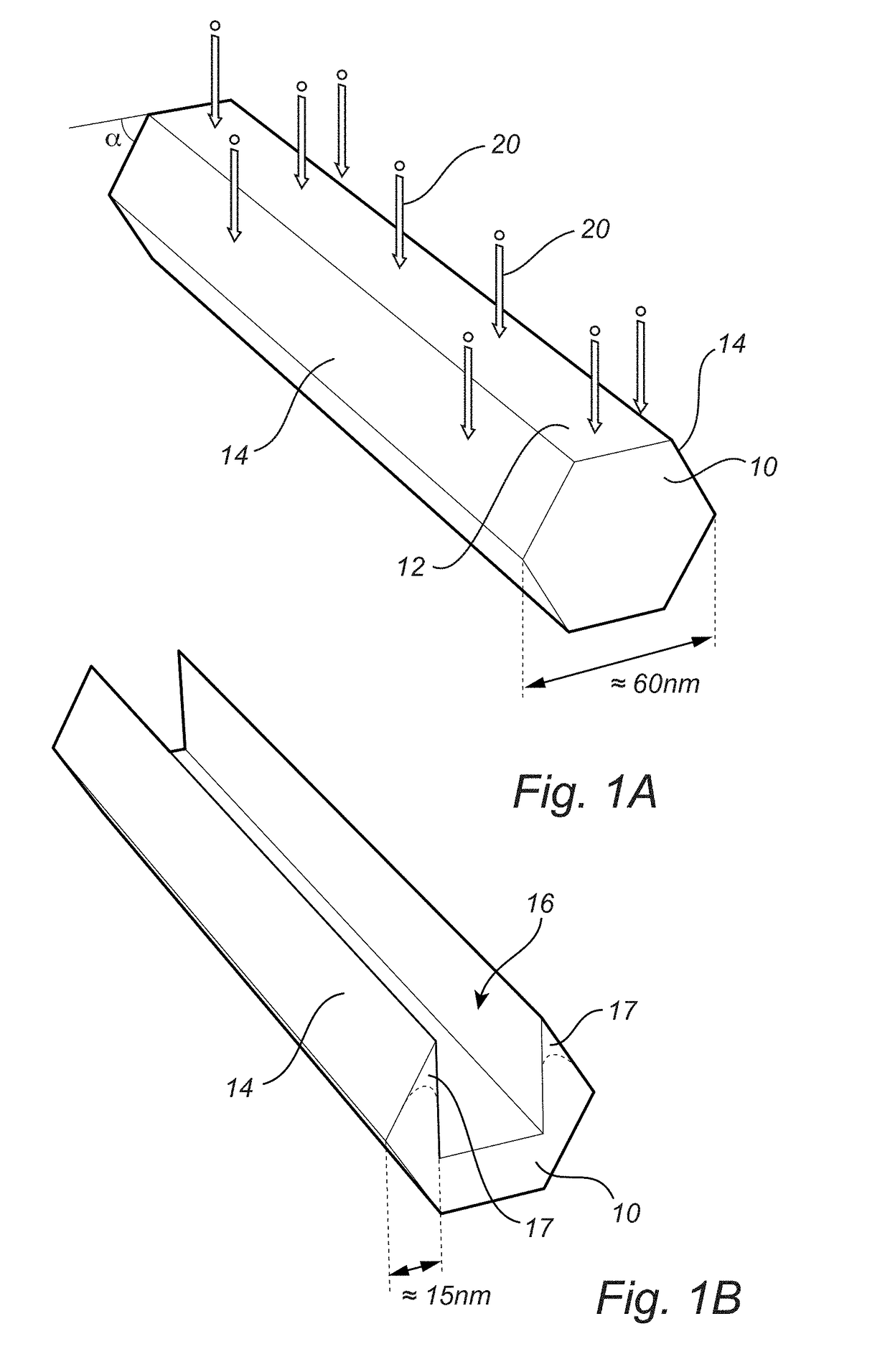
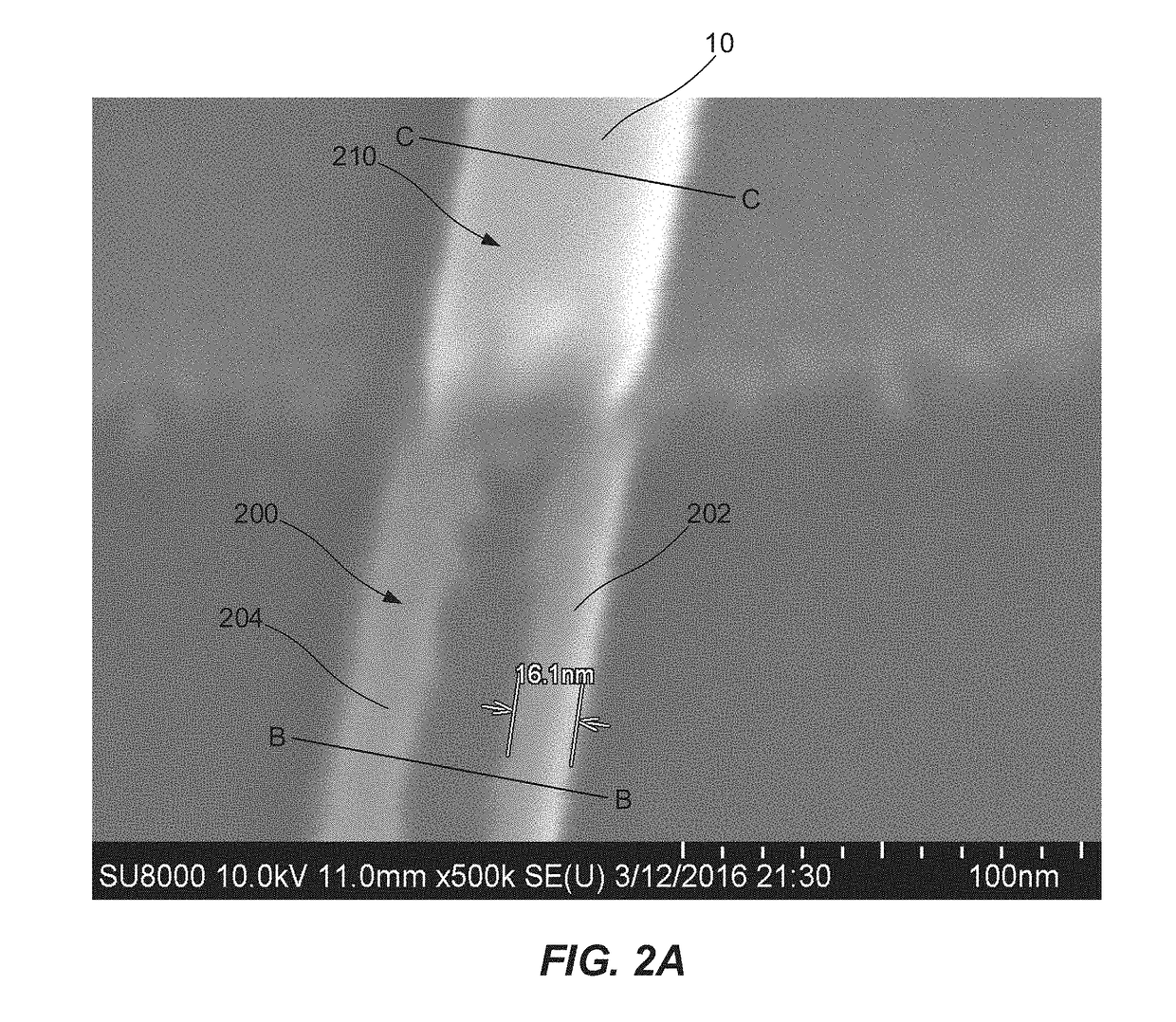
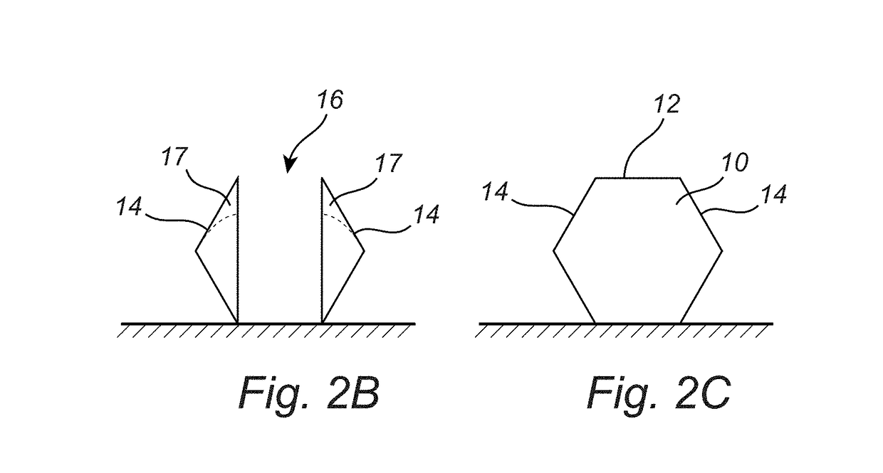
[0060]The present invention is directed towards selective etching of nanostructures. The inventors have surprisingly discovered that by subjecting a nanostructure, with in relation to each other inclined surfaces, for dry etching with a particle beam being substantially perpendicular to a main surface of delimited by inclined surfaces, a recess is formed between the inclined surfaces. The particle beam etches the structure surface less when the angle towards the particle beam is smaller or larger than 90°. Thus, the incl...


PUM

PropertyMeasurementUnit
inclination angleaaaaaaaaaa
diameteraaaaaaaaaa

Abstract

The present invention relates to a method for selective etching of a nanostructure (10). The method comprising: providing the nanostructure (10) having a main surface (12) delimited by, in relation to the main surface (12), inclined surfaces (14); and subjecting the nanostructure (10) for a dry etching, wherein the dry etching comprises: subjecting the nanostructure (10) for a low energy particle beam (20) having a direction perpendicular to the main surface (12); whereby a recess (16) in the nanostructure (10) is formed, the recess (16) having its opening at the main surface (12) of the nanostructure (10).

Description

TECHNICAL FIELD[0001]The present invention relates to selective etching of nanostructures.BACKGROUND[0002]The interest in manufacturing devices, e.g. advanced semiconductor devices, having dimensions below 100 nm have for the last decades been growing. Today a lateral size of advanced semiconductor devices, i.e. electronic components such as transistors, is already at and even below 20 nm. However, fabrication of structures with lateral size below 20 nm is hard to achieve with present processes. For instance, the spatial resolution of ultraviolet lithography, UVL, which is commonly used for manufacturing semiconductor devices in industry, is limited. Therefore, alternative novel approaches are required to overcome such challenges and to allow fabrication of nanostructures with lateral size below 20 nm.SUMMARY OF THE INVENTION[0003]In view of the above, it is an object of the present invention to provide a method for fabricating structures, especially semiconductor, in the sub 20 nm ...

Claims


Application Information

Patent Timeline
Patent Type & Authority Applications(United States)
IPC IPC(8): H01L21/3065H01L29/06H01L29/66H01L29/775H01L29/78
CPCH01L21/3065H01L29/0673H01L29/66439H01L29/775H01L29/785H01L29/66795H01L2029/7858B82Y40/00H01L21/30621H01L21/3086B81C1/00626B82Y10/00
Inventor KHAN, MD SABBIR AHMEDSUNDQVIST, JONASSUYATIN, DMITRY
Owner ALIXLABS AB
Learn More