
Receiver architecture for digital isolators employing notch filters for common mode transient immunity

a technology of transient immunity and receiver architecture, applied in the field of isolation technology, can solve problems such as interference with information accuracy and the need for isolation barriers

Active Publication Date: 2019-02-28
SKYWORKS SOLUTIONS INC
View PDF5 Cites 19 Cited by
  • Summary
  • Abstract
  • Description
  • Claims
  • Application Information

AI Technical Summary

Benefits of technology

This patent describes a differential receiver circuit that includes a band-stop filter to remove energy in a specific frequency range. The circuit includes filters to remove energy in a higher carrier frequency range and a lower notch frequency range. The circuit also includes a buffer circuit and a notch filter to create a second stopband around the notch frequency. The circuit has a constant propagation delay regardless of the events being attenuated. The invention also includes a method of receiving signals using the differential receiver circuit. In one embodiment, a method of receiving signals involves band-stop filtering energy in a first frequency range, high-pass filtering energy in a second frequency range, and then removing the carrier wave using a notch filter to recover digital data encoded in the received signal.

Problems solved by technology

During normal operation, a large DC or transient voltage difference may exist between the power domain of the processor system and the power domain of the load system, thus requiring an isolation barrier between the processor system and the load system.
However, such communication is susceptible to common mode transients that can interfere with the accuracy of the information transmitted across the isolation channel.

Method used


Image

  • Receiver architecture for digital isolators employing notch filters for common mode transient immunity
  • Receiver architecture for digital isolators employing notch filters for common mode transient immunity
  • Receiver architecture for digital isolators employing notch filters for common mode transient immunity

Examples


Embodiment Construction

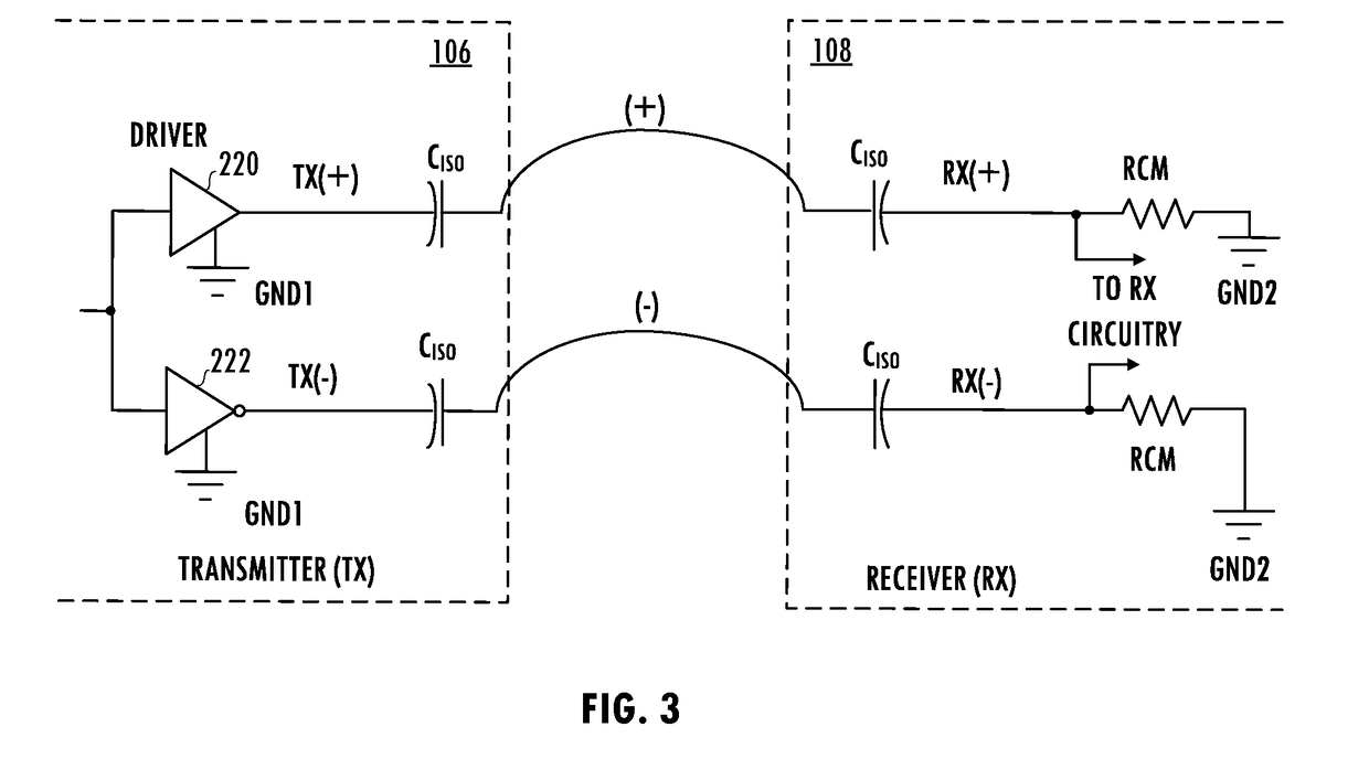
[0004]In at least one embodiment of the invention, a differential receiver circuit includes a band-stop filter having a stopband fSB around a notch frequency fn of a received signal. The differential receiver circuit includes a first high-pass filter coupled in series with the band-stop filter. The notch frequency fn is less than a carrier frequency fc of a signal received by the differential receiver circuit. The band-stop filter may include a buffer circuit and a notch filter coupled in series with the buffer circuit. The notch filter may have a second stopband around the notch frequency fn. The differential receiver circuit may have a propagation delay that is independent of a pulse width of common mode transient energy attenuated by the differential receiver circuit.

[0005]In at least one embodiment of the invention, a method of receiving a signal includes band-stop filtering a first version of a received signal to attenuate energy in a stopband fSB around a notch frequency fn. T...


PUM


Abstract

A technique for attenuating common mode transient events uses a differential receiver circuit including a band-stop filter having a stopband fSB around a notch frequency fn of a received signal. The differential receiver circuit includes a first high-pass filter coupled in series with the band-stop filter. The notch frequency fn is less than a carrier frequency fc of a signal received by the differential receiver circuit. The band-stop filter may include a buffer circuit and a notch filter coupled in series with the buffer circuit. The notch filter may have a second stopband around the notch frequency fn. The differential receiver circuit may have a propagation delay that is independent of a pulse width of common mode transient energy attenuated by the differential receiver circuit.

Description

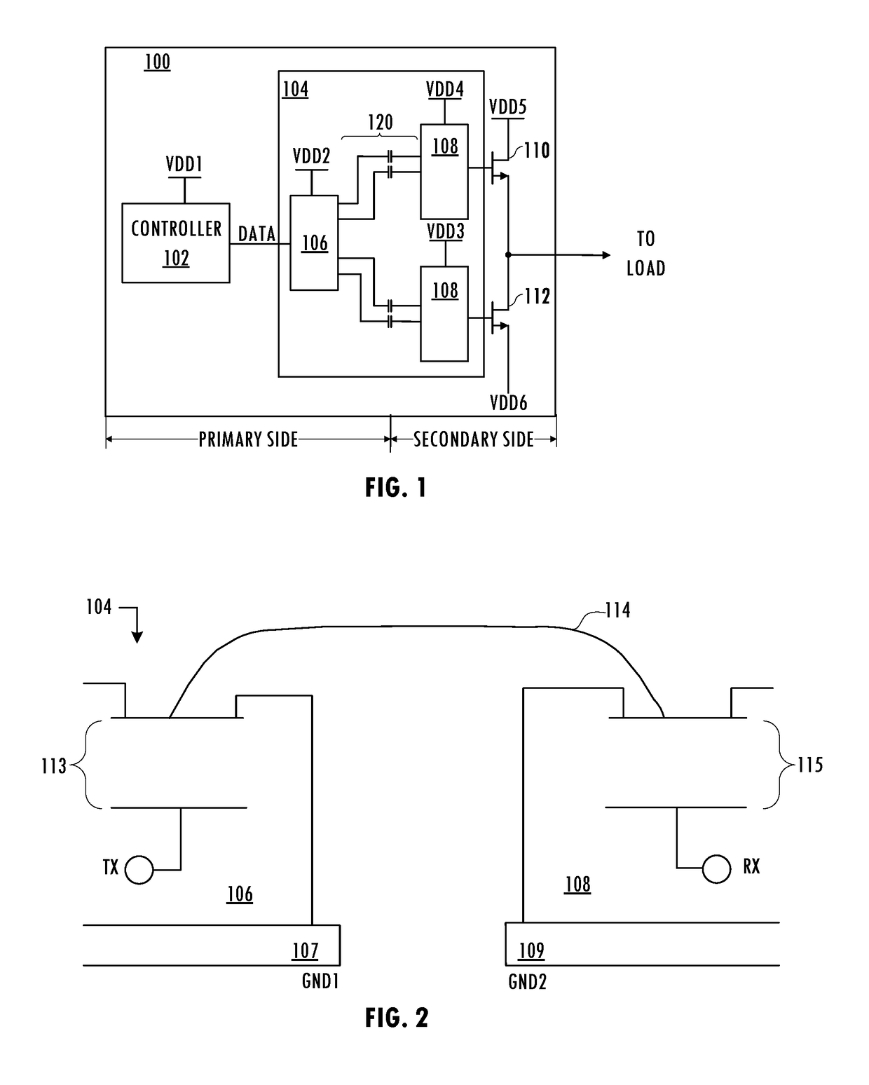
BACKGROUNDField of the Invention[0001]The invention relates to isolation technology and more particularly to communication across an isolation channel.Description of the Related Art[0002]In a typical control application, a processor system provides one or more control signals for controlling a load system. During normal operation, a large DC or transient voltage difference may exist between the power domain of the processor system and the power domain of the load system, thus requiring an isolation barrier between the processor system and the load system. For example, one domain may be “grounded” at a voltage that is switching with respect to earth ground by hundreds or thousands of volts. Even when the expected voltage difference between the domains is small in normal operation, isolation increases safety in some applications. For example, in a biomedical application that includes electrodes taped to a patient's body, even if a measurement device is properly grounded, isolation inc...

Claims


Application Information

Patent Timeline
IPC IPC(8): H04L25/02H03H11/04H03H7/06H03H7/01H03H11/38H04L25/08H04L27/06H04B1/10
CPCH04L25/0294H03H11/04H03H7/06H03H7/0161H03H11/38H04L25/08H04L27/06H04B1/1036H03H2007/013H03H2011/0488H04B2001/1063H04B1/1027H03H7/065H04L25/085H04L25/0272H04L25/0292
Inventor AL-SHYOUKH, MOHAMMADMASTOVICH, STEFAN
Owner SKYWORKS SOLUTIONS INC
Learn More