Oil, water, gas and solid particle separation in oil and/or gas production

Active Publication Date: 2019-02-28
FOURPHASE
View PDF0 Cites 7 Cited by
  • Summary
  • Abstract
  • Description
  • Claims
  • Application Information

AI Technical Summary

Benefits of technology

The patent describes a method for separating oil and water using a gas floder and a first separator. The gas floder creates gas bubbles in the oil / water mixture to collect droplets of oil. The separated gas is then returned to the gas floder to create the gas supply. A second portion of the gas is optionally returned to the separation tank to prevent the level of liquid from rising to the gas outlet. The method also includes using a coalescer or a barrier of fine mesh to remove oil that may be carried as a fine mist within the gas and improve the oil / gas separation. The overall effect of the method is to enhance the separation of oil and water from the hydrocarbon-containing fluid.

Problems solved by technology

Such productions units are very expensive systems and platform space comes at a premium.
In addition, consumables required for the process require storage space, which adds to their purchase price and so increases the overall cost of their use.
Today this often requires a lot of equipment to carry out these separations in sequential steps.
As a result, a large footprint or platform area is required which increases the overall cost of the system.
This can significantly increase the construction cost of the production facility or platform.

Method used


Image

  • Oil, water, gas and solid particle separation in oil and/or gas production
  • Oil, water, gas and solid particle separation in oil and/or gas production

Examples


Embodiment Construction

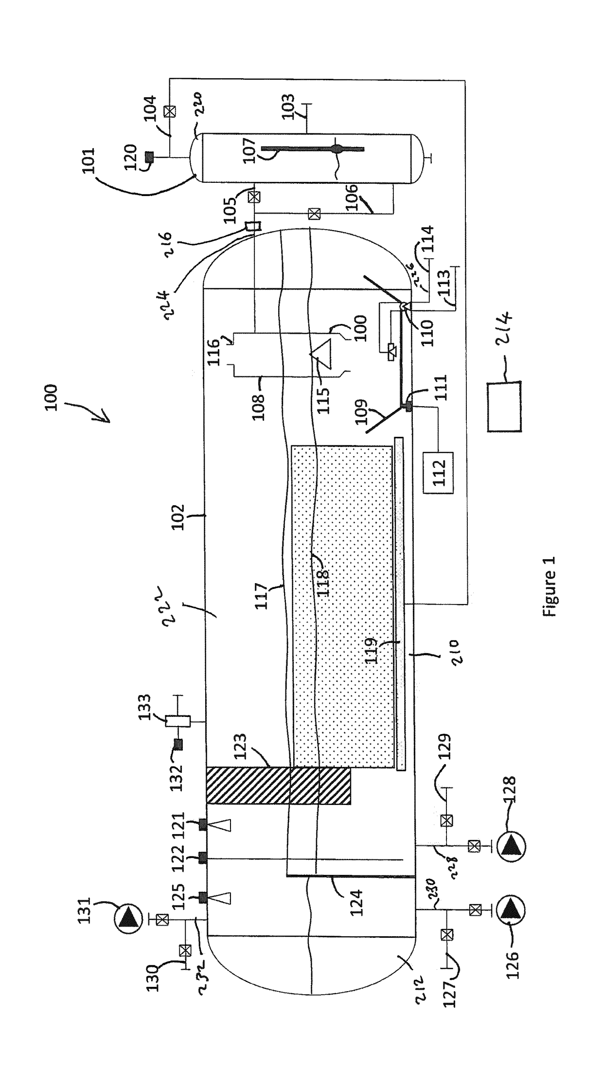
[0047]Referring to FIG. 1 there is shown a schematic illustration of an oil, water, gas and solids separation system, designated generally as 100, which constitutes an apparatus for separating oil, water, gas and solid particles from a hydrocarbon-containing fluid produced from an oil and / or gas production facility in accordance with an embodiment of the present invention. The separation system 100 comprises an inlet separator tank 101 and a larger separation tank 102 downstream thereof. Oil, water, gas and solids (usually sand) enter the inlet separator tank 101 via inflow conduit 103. This inflow conduit 103 contains production flow from a production manifold, not shown, that has come from an oil well or group of oil wells. This manifold may also choke the flow so that the pressure of the mixture entering the inlet separator tank 101 is regulated.

[0048]In accordance with the first and second aspects of the present invention as identified above, the separation tank 102 is configure...


PUM

PropertyMeasurementUnit
Pressureaaaaaaaaaa
Flow rateaaaaaaaaaa
Volumeaaaaaaaaaa

Abstract

An apparatus for, and a method of, separating oil, water, gas and solid particles (usually sand) from a hydrocarbon-containing fluid produced from an oil and / or gas production facility. In particular, this invention relates to an apparatus and method for the separation of oil, water, gas and solid particles from a well or group of wells using an integrated apparatus which significantly reduces the space required on the production platform or rig and recycles produced gas to improve process efficiency while reducing cost.

Description

FIELD OF THE INVENTION[0001]The present invention relates to an apparatus for, and a method of, separating oil, water, gas and solid particles (usually sand) from a hydrocarbon-containing fluid produced from an oil and / or gas production facility. In particular, this invention relates to an apparatus and method for the separation of oil, water, gas and solid particles from a well or group of wells using an integrated apparatus which significantly reduces the space required on the production platform or rig and recycles produced gas to improve process efficiency while reducing cost.BACKGROUND[0002]Many offshore oil and gas fields are developed and produced using a multi-well platform. In general a template is placed on the seabed, which comprises slots and a well is drilled through each slot. It is not uncomment to have 10 to 20 wells drilled from a single template. Each well will be drilled to hit a particular reservoir target or targets. The trajectory of the wells can be very diffe...

Claims


Application Information

Patent Timeline
IPC IPC(8): E21B43/34B01D21/26B01D21/30B01D21/24B01D21/34B01D19/00B01D17/12B01D17/02B01D46/00B01D21/00
CPCE21B43/34B01D21/267B01D21/302B01D21/2472B01D21/34B01D19/0057B01D17/12B01D17/0205B01D17/0211B01D17/0214B01D46/0031B01D21/0096B01D17/00B01D17/02B01D17/04B01D19/00E21B43/35B01D17/045B01D17/0217
Inventor AREFJORD, ANDERSBRUNTVEIT, JORGEN
Owner FOURPHASE
Why Eureka
Try Eureka