Variable valve lift actuator of engine
a technology of variable valve and actuator, which is applied in the direction of valve arrangement, non-mechanical valve, machines/engines, etc., can solve the problems of increasing the number of parts and deteriorating the operating performance, and achieves the effects of reducing costs, reducing operating performance and reducing rigidity
- Summary
- Abstract
- Description
- Claims
- Application Information
AI Technical Summary
Benefits of technology
Problems solved by technology
Method used
Image
Examples
embodiment 1
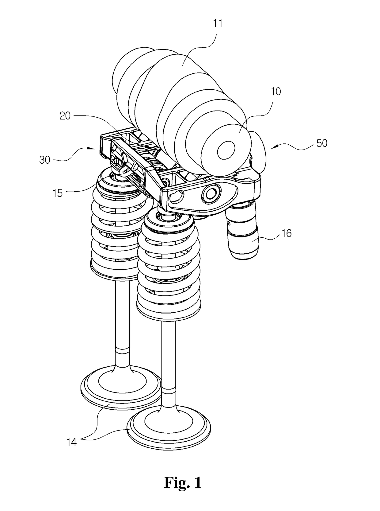
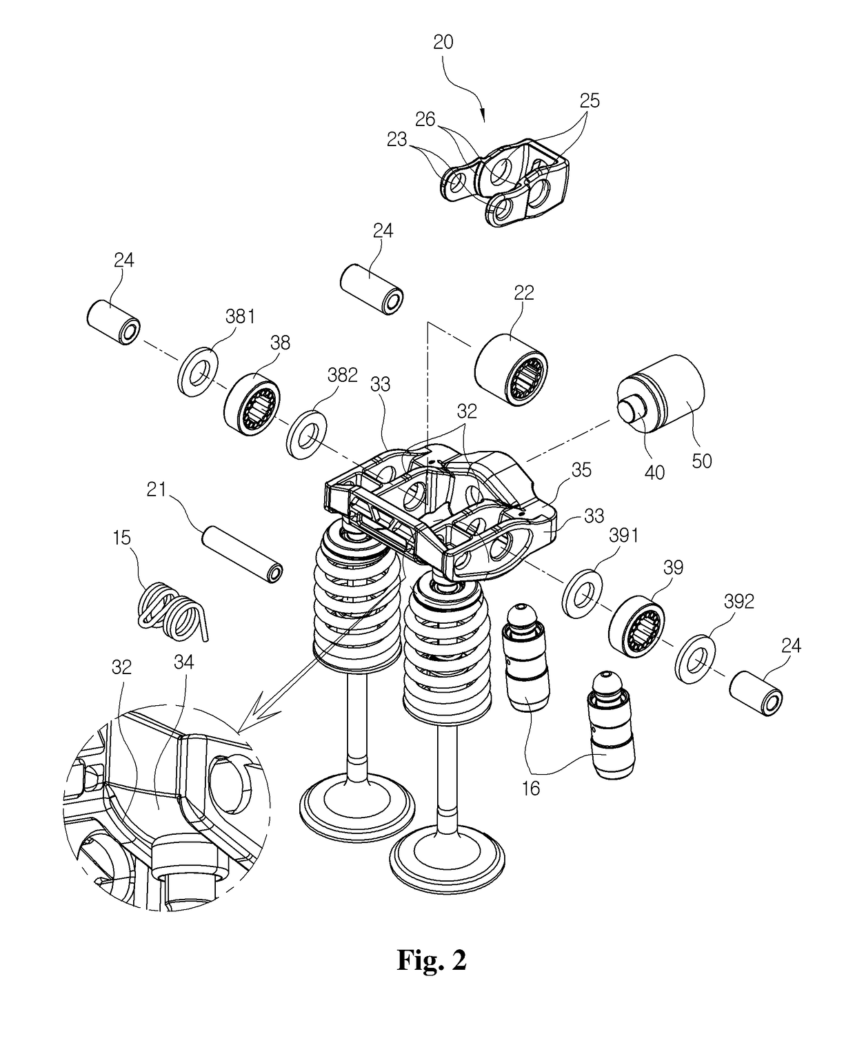
[0043]FIG. 1 is a perspective view of a variable valve lift actuator of an engine according to a preferred embodiment of the present invention. FIG. 2 is a partially exploded perspective view of the variable valve lift actuator shown in FIG. 1.
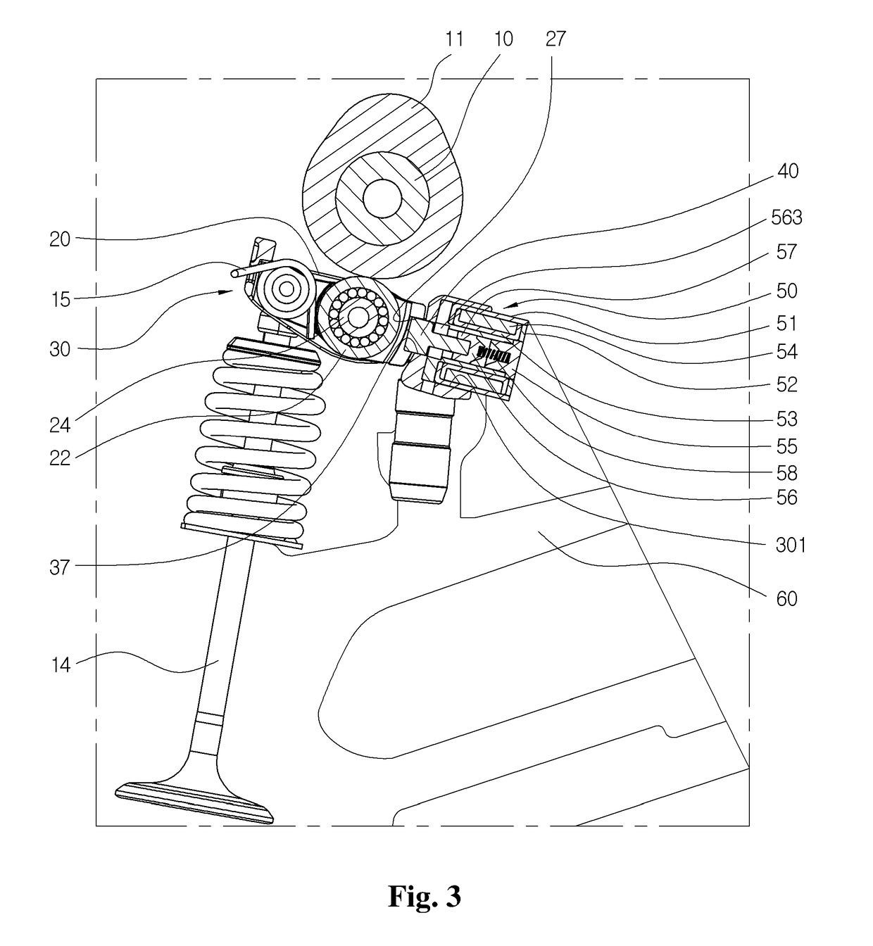
[0044]In addition, FIG. 3 is an enlarged sectional view showing a state of installing the variable valve lifting actuator shown in FIG. 1 in a cylinder head.
[0045]Hereinafter, the terms indicating a direction such as “left”, “right”, “front”, “rear”, “upper” and “lower” are defined to indicate directions on the basis of a state shown in drawings, respectively.
[0046]As shown in FIGS. 1 and 2, the variable valve lift actuator of the engine according to a preferred embodiment of the present invention includes a first body 20 rotating in a predetermined angular range by a rotational motion of a cam 11 coupled to a camshaft 10, a second body 30 for opening / closing a valve 14 or maintaining the valve 14 in a closed state based on a connection state ...
embodiment 2
[0121]Next, the configuration of the variable valve lift actuator of the engine according to the second embodiment will be described in detail with reference to drawings.
[0122]FIG. 7 is a perspective view of a variable valve lift actuator of an engine according to the second embodiment of the present invention.
[0123]As shown in FIG. 7, the variable valve lift actuator of the engine according to the second embodiment of the present invention is similar to the configuration of the first embodiment. However, some configurations may be added to control the lift degree of the valve in two stages of the high-speed mode or the low-speed mode based on an operating condition of the engine.
[0124]In other words, the camshaft 10 may be provided therein with a high-speed cam 12 for controlling the lift degree of the valve 14 to be maximum in a high-speed and high-load state of the engine, and a low-speed cam 13 for controlling the lift degree of the valve 14 to be minimum in a low-speed and low-...
embodiment 3
[0147]FIG. 10 is a perspective view of a variable valve lift actuator of an engine according to a third embodiment of the present invention.
[0148]According to a third embodiment of the present invention, as shown in FIG. 10, the variable valve lift actuator of the engine is similar to the configurations of the first and second embodiments. However, an opening 341 may be formed on both sides of the front wall 31 of the second body, such that the lower end of the rotary shaft 21 makes contact with the upper end of the valve 21 between the inner side wall 32 and the outer side wall 33.
[0149]Accordingly, the rotary shaft 21 downwardly presses the upper end of the valve 14 according to the rotational motion of the second body 30, thereby enabling the valve 14 to be opened and closed.
[0150]To this end, the rotary shafts 21 may extend to be coupled to the outer side walls 33 on both sides of the second body 30.
[0151]In addition, contact surfaces 211 processed in a planar shape may be forme...
PUM
 Abstract
Description
Claims
Application Information
 - R&D
- Intellectual Property
- Life Sciences
- Materials
- Tech Scout
- Unparalleled Data Quality
- Higher Quality Content
- 60% Fewer Hallucinations
Browse by: Latest US Patents, China's latest patents, Technical Efficacy Thesaurus, Application Domain, Technology Topic, Popular Technical Reports.
© 2025 PatSnap. All rights reserved.Legal|Privacy policy|Modern Slavery Act Transparency Statement|Sitemap|About US| Contact US: help@patsnap.com


