Radiography system and method for operating radiography system
a radiography system and radiography system technology, applied in the field of radiography system and method for operating radiography system, can solve the problems of difficult to obtain a radiographic image of the patient, non-use cassettes do not normally operate,
- Summary
- Abstract
- Description
- Claims
- Application Information
AI Technical Summary
Benefits of technology
Problems solved by technology
Method used
Image
Examples
first embodiment
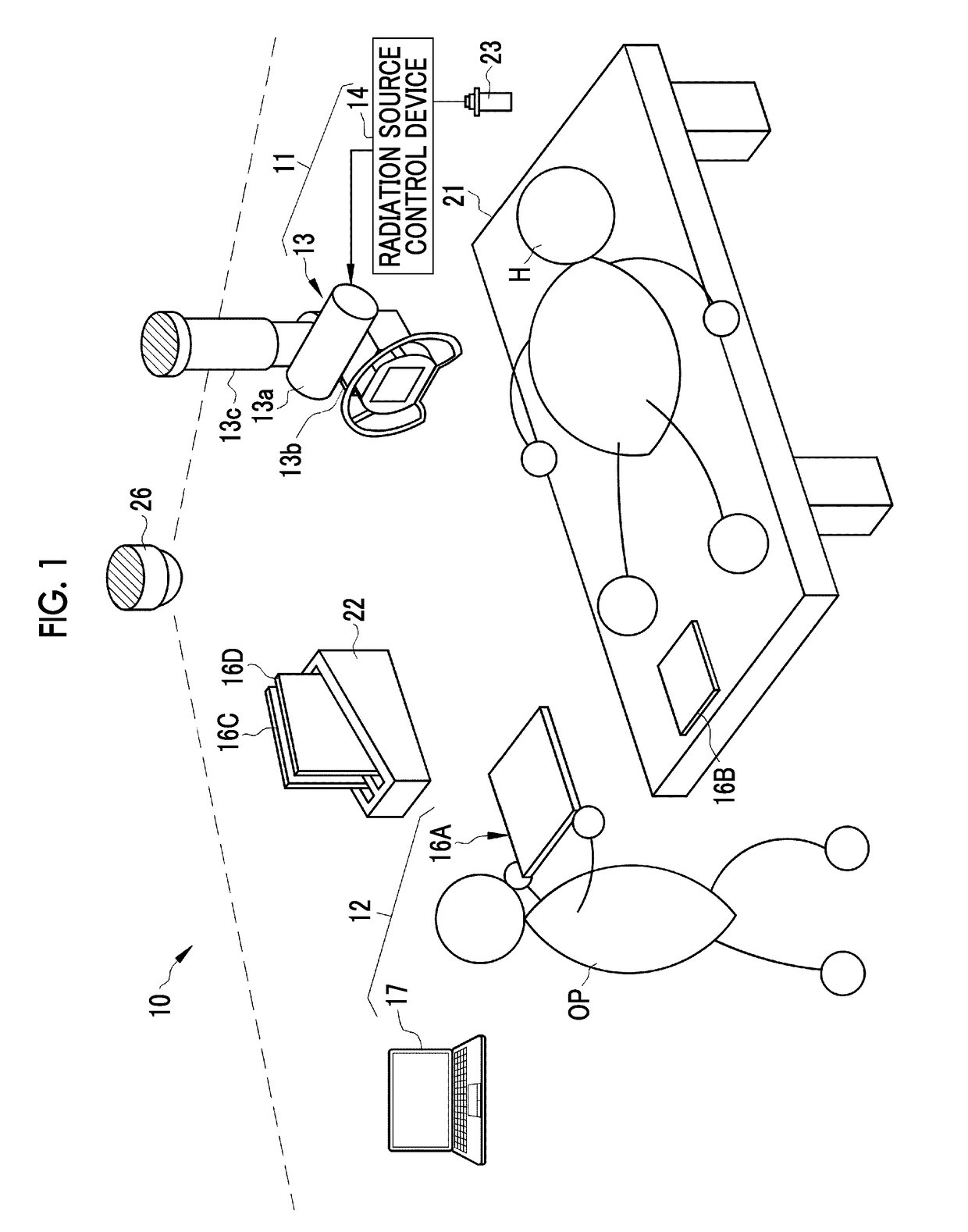
[0075]In FIG. 1, an X-ray imaging system 10 that uses X-rays as radiation includes an X-ray generation apparatus 11, an X-ray imaging apparatus 12, and a camera 26. The X-ray generation apparatus 11 includes an X-ray source 13 corresponding to a radiation source and a radiation source control device 14 that controls the X-ray source 13. The X-ray imaging apparatus 12 includes an electronic cassette 16 and a console 17.
[0076]FIG. 1 illustrates an aspect in which X-ray imaging is performed for a subject H that lies on a bed 21 using the electronic cassette 16 in an imaging room in which the X-ray imaging system 10 is installed. The electronic cassette 16 is placed on, for example, the bed 21 or is held in the arms of the subject H depending on an imaging part and then imaging is performed. The X-ray imaging illustrated in FIG. 1 is free imaging without using an imaging stand.
[0077]The imaging room is equipped with an upright imaging stand (not illustrated) or a decubitus imaging stand...
second embodiment
[0175]As in a second embodiment illustrated in FIGS. 24 and 25, in a case in which the use cassette is absent in the camera image 76, the emission of X-rays may be prohibited. For the process in a case in which the use cassette is absent in S2400 of FIG. 20, in the example illustrated in FIG. 23, only the process (S2401A) of displaying the message 81 indicating that the use cassette is absent is performed. In the second embodiment, as illustrated in FIG. 24, in addition to S2401A, a process of prohibiting the irradiation operation of the X-ray generation apparatus 11 is performed (S2402A).
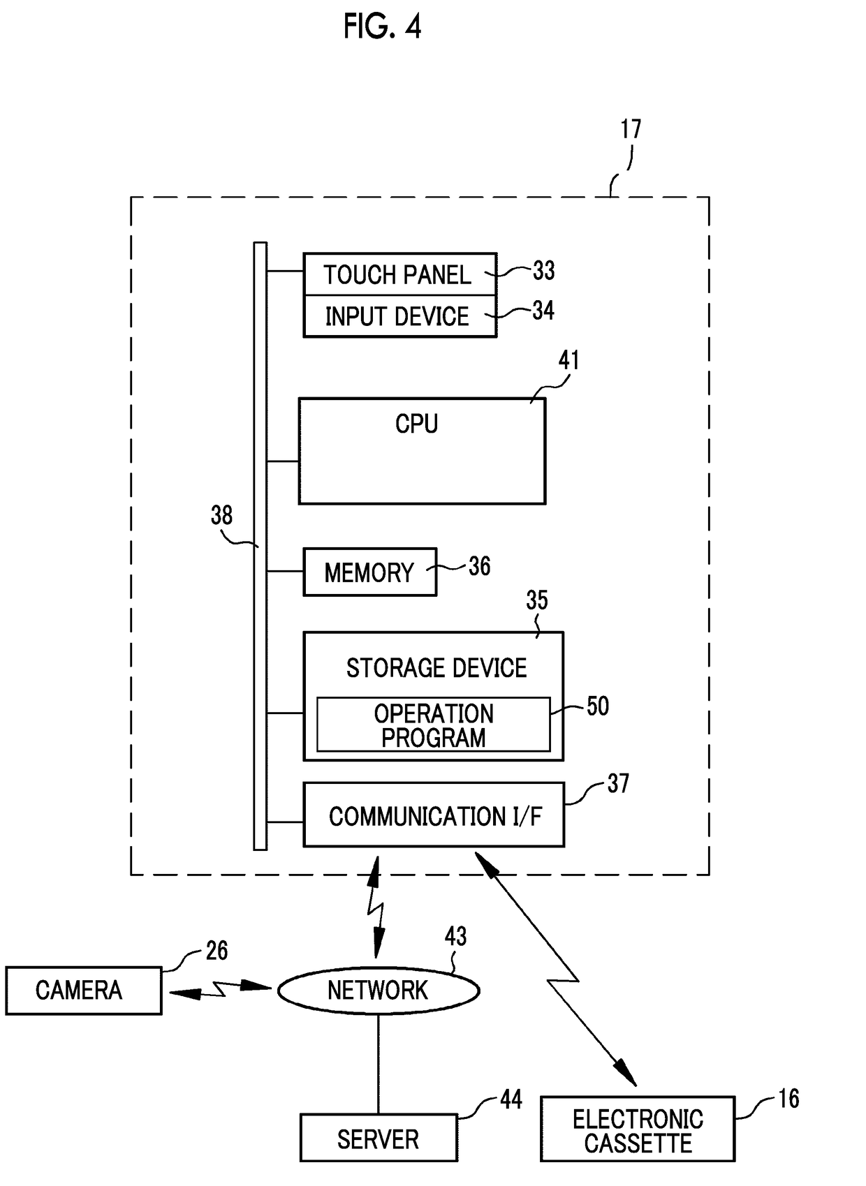
[0176]In this case, as illustrated in FIG. 25, the console 17 is provided with an irradiation prohibition signal output unit 82. In a case in which the operation program 50 is executed, the CPU 41 functions as the irradiation prohibition signal output unit 82. The console 17 and the X-ray generation apparatus 11 are connected such that they communicate with each other in a wired manner or wirelessl...
third embodiment
[0177]In a third embodiment illustrated in FIGS. 26 to 29, the identification information acquisition unit 73 detects identification light emitted from an indicator 84 that is provided in the electronic cassette 16 and acquires the first cassette ID from the camera image 76. In the first embodiment, for the first cassette ID acquisition process in S1700 of FIG. 20, the first cassette ID is acquired from the ID marker 32 as illustrated in S1700A of FIG. 21. Instead of acquiring the first cassette ID from the ID marker 32 as in the first embodiment, the identification information acquisition unit 73 may acquire the first cassette ID from the identification light emitted from the indicator 84 as in the third embodiment.
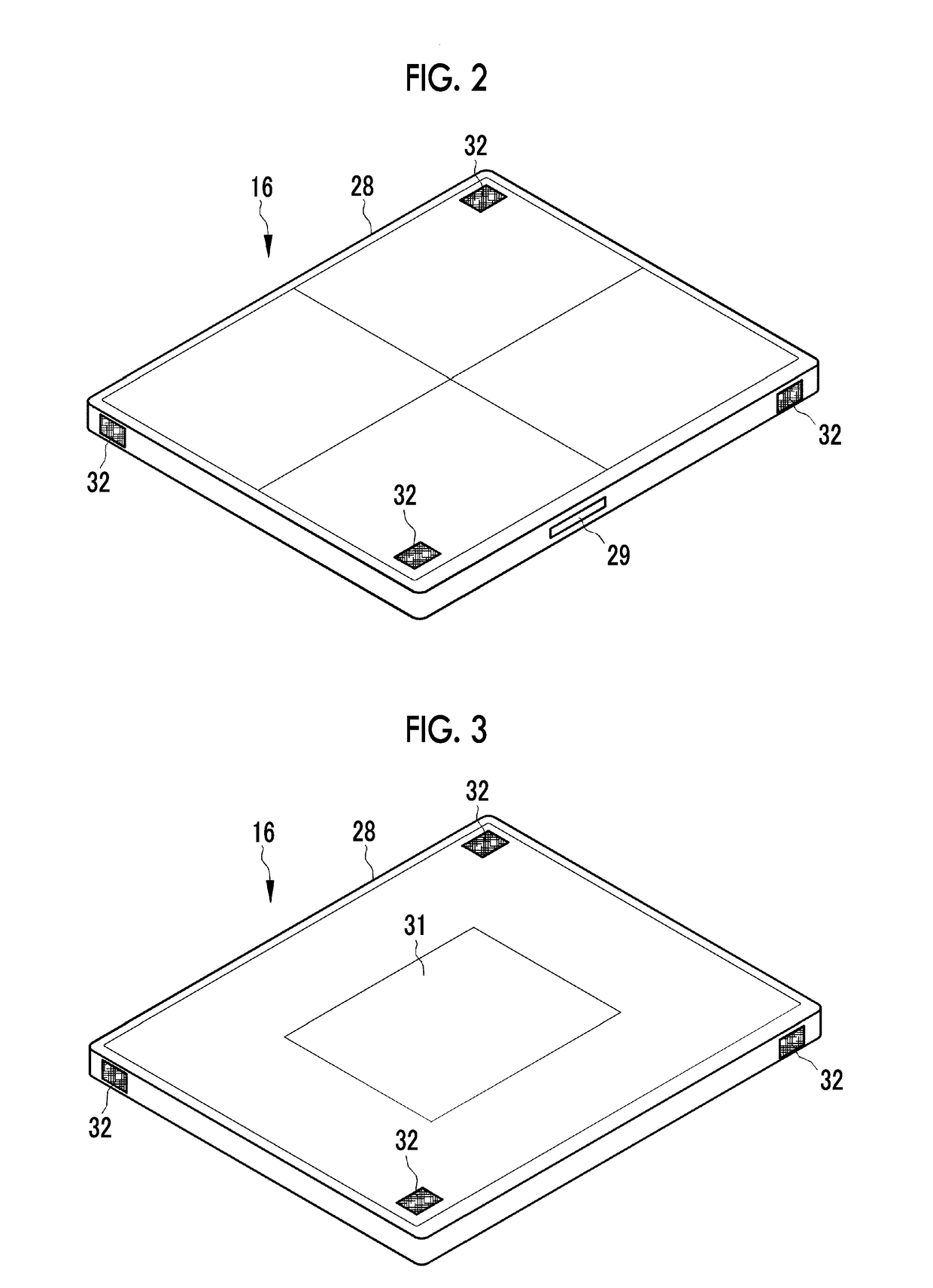
[0178]As illustrated in FIGS. 26 and 27, in the third embodiment, for example, the indicator 84 is provided at the center of each of four side surfaces of the housing 28 of the electronic cassette 16. The indicator 84 is a light source such as a light emitting diode (LED...
PUM
 Abstract
Description
Claims
Application Information
 - R&D
- Intellectual Property
- Life Sciences
- Materials
- Tech Scout
- Unparalleled Data Quality
- Higher Quality Content
- 60% Fewer Hallucinations
Browse by: Latest US Patents, China's latest patents, Technical Efficacy Thesaurus, Application Domain, Technology Topic, Popular Technical Reports.
© 2025 PatSnap. All rights reserved.Legal|Privacy policy|Modern Slavery Act Transparency Statement|Sitemap|About US| Contact US: help@patsnap.com


