
Non-powered passive braking device using centrifugal force

Active Publication Date: 2019-02-07
CHUNG ANG UNIV IND ACADEMIC COOP FOUND
View PDF9 Cites 2 Cited by
  • Summary
  • Abstract
  • Description
  • Claims
  • Application Information

AI Technical Summary

Benefits of technology

The present invention is about a non-powered braking device that uses centrifugal force to compensate for gravity. It has low inertia, works in both directions, and has a structure that allows for controlling braking speed.

Problems solved by technology

However, the active braking device has problems in which the system is complex and a complex controller is additionally required.
Since functions of most passive braking devices are affected by a direction of gravity, it is hard to apply the passive braking device to robots with a high degree of freedom.
Further, since mechanism of the conventional passive braking device is heavy and bulky, and braking torque thereof is applied only in one direction, the passive braking device has a problem in being applied to a multi-body dynamic system.
In addition, since a spring structure of the passive braking device is not completely independent with respect to a direction of gravity, the performance of the passive braking device is affected by gravity when used in a joint of the robot, and thus the development of a passive braking device having a structure capable of compensating for gravity is needed.

Method used


Image

  • Non-powered passive braking device using centrifugal force
  • Non-powered passive braking device using centrifugal force
  • Non-powered passive braking device using centrifugal force

Examples


Embodiment Construction

[0021]Exemplary embodiments of the present invention will be illustrated in the accompanying drawings and described in detail in the written description, but the embodiments may be changed and have many alternative forms. However, the present invention is not limited to particular modes of practice, and it should be appreciated that all changes, equivalents, and substitutes not departing from the spirit and technical scope of embodiments are encompassed in the embodiments. In the description of the embodiments, certain detailed descriptions of the related art will be omitted when it is deemed that the detailed descriptions unnecessarily obscure the essence of the inventive concept.

[0022]Although the terms first, second, etc. are used to describe various components, the components are not limited by the terms. The terms are used to only to distinguish one component from another.

[0023]The terminology used herein is for the purpose of describing particular embodiments only and is not i...


PUM


Abstract

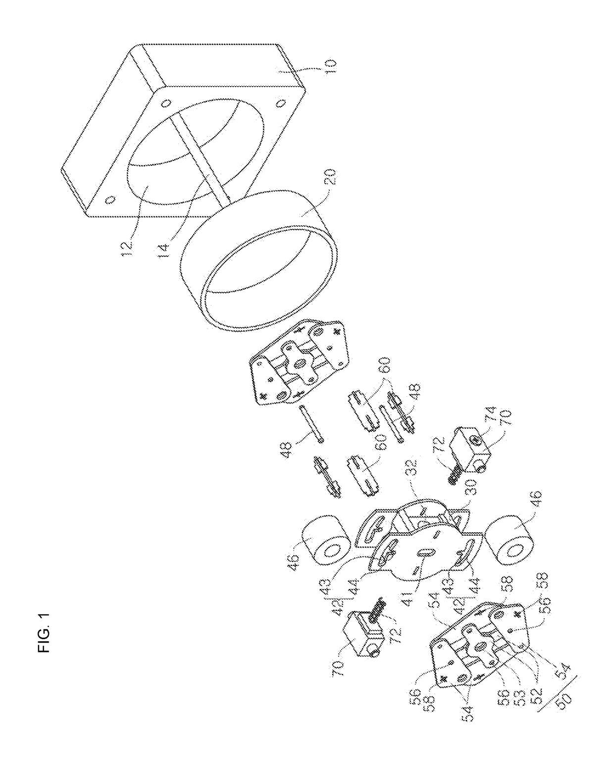
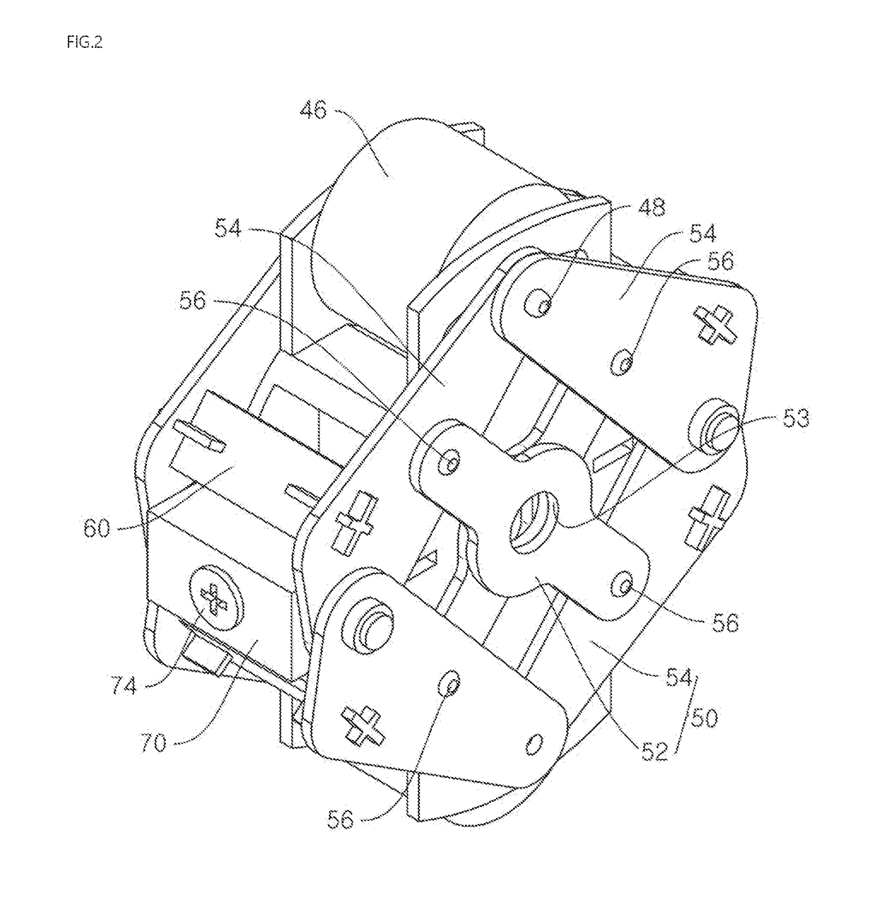
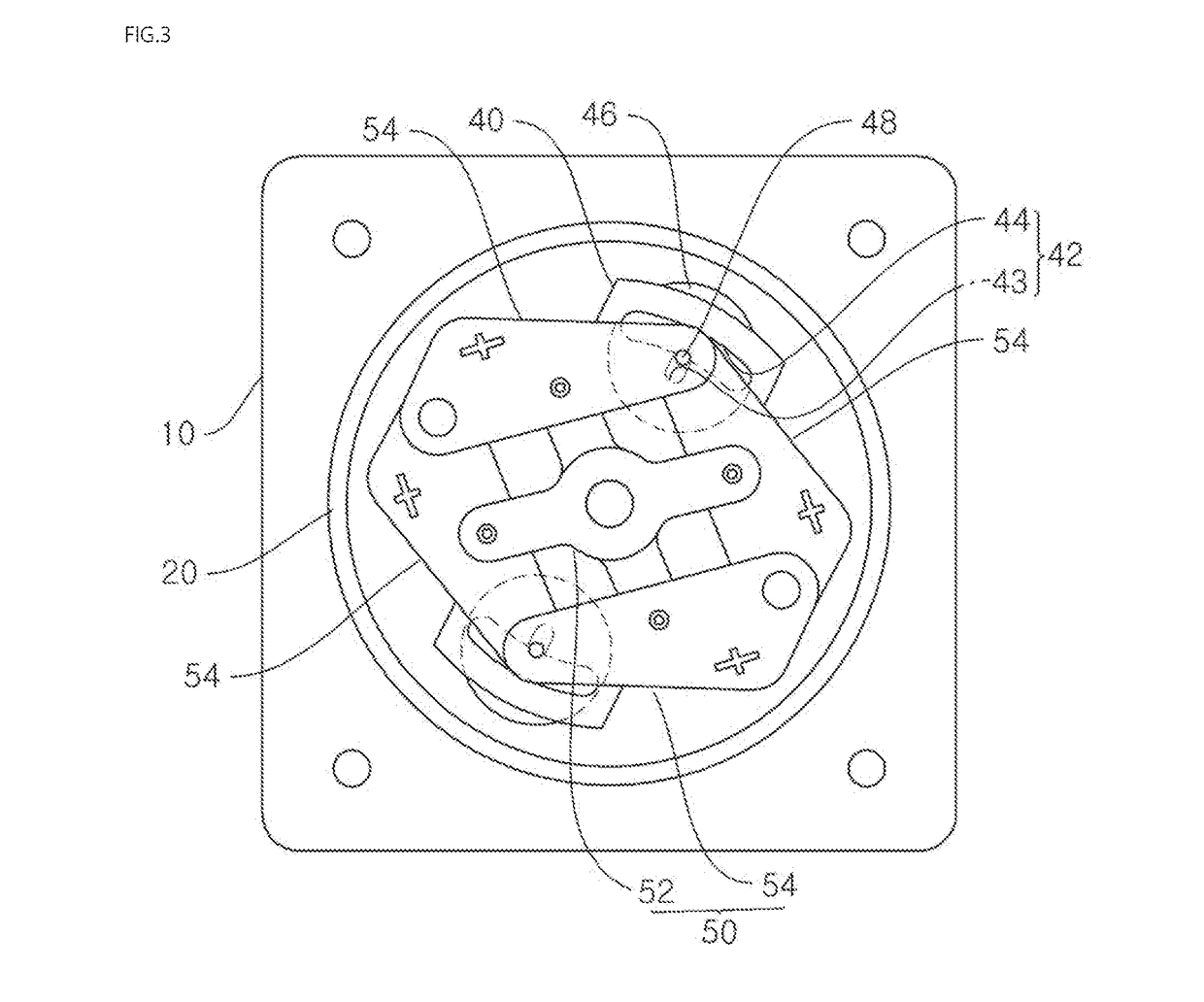
The present invention relates to an unpowered braking device using centrifugal force. The present invention may comprise: a housing; a brake drum installed inside the housing; a plurality of braking links rotatably installed on a rotating shaft of the housing and connected such that both ends thereof can expand and contract by means of centrifugal force; brake rollers provided on both ends of the braking links, respectively, such that, when the braking links expand, the brake rollers are forced against the inner walls of the brake drums and thereby generate braking force / torque; and an elastic member for providing elastic force such that both ends of the braking links, which have expanded, can contract.

Description

TECHNICAL FIELD[0001]The present invention relates to a non-powered passive braking device using a centrifugal force, and more specifically, to a non-powered passive braking device using a centrifugal force which may compensate for gravity using a centrifugal force, have low inertia, bi-directionally perform braking, and control a braking velocity.BACKGROUND ART[0002]An active braking device is widely used to control a joint angular velocity. However, the active braking device has problems in which the system is complex and a complex controller is additionally required.[0003]In contrast, a passive braking device is superior to the active braking device in terms of weight, compactness, energy efficiency, and responsiveness. Further, since the passive braking device is inherently safe, a complex fail-safe framework is not required. Generally, the passive braking device using a centrifugal force is used in a seat belt, an elevator, a fishing rod, and the like.[0004]Since functions of m...

Claims


Application Information

Patent Timeline
IPC IPC(8): F16D51/22F16D59/00F16D63/00F16D65/10
CPCF16D51/22F16D59/00F16D63/00F16D65/10F16D2121/14F16D2127/002F16D2129/043F16D51/18F16D65/08
Inventor SHIN, DONG JUN
Owner CHUNG ANG UNIV IND ACADEMIC COOP FOUND
Learn More