Axle unit

a technology of axle unit and clamping parts, which is applied in the direction of resilient suspensions, vehicle springs, vehicle components, etc., can solve the problems of increasing the tendency of weld cracks, and increasing the number of additional components, so as to reduce the stress on the material of the clamping parts, reduce the tendency of weld cracks, and improve the overall service life of the axle unit

Active Publication Date: 2019-02-07
SAF HOLLAND GMBH
View PDF0 Cites 2 Cited by
  • Summary
  • Abstract
  • Description
  • Claims
  • Application Information

AI Technical Summary

Benefits of technology

The patent text describes a clamping system for a control arm and axle tube. The system uses wedge portions that increase in thickness towards the distal end, which is the end that faces the opposite clamping part. The clamping part is displaced to bring the clamping unit into engagement with the control arm and axle tube. The wedge portions can also have conical or tapered outer faces to prevent uneven wear. In another embodiment, the control arm is curved and has concave recesses for holding the clamping unit securely. The technical effect of this patent text is a more robust and secure clamping system for control arms and axle tubes.

Problems solved by technology

The disadvantage of these U-shaped brackets is the large number of additional components that are required to achieve a sufficiently sturdy seating of the longitudinal control arm on the axle tube and simultaneously prevent rotation of the axle tube as far as possible.
The disadvantage of an integral bond is that said bond cannot be separated without extensively destroying the material of the control arm or of the axle tube, and that, during the welding process, a change in the material structure takes place on the longitudinal control arm and on the axle tube in the region of the weld zone, wherein in particular the brittle fracture tendency increases, and material-internal stresses can arise, which promote crack formation in the weld zone.

Method used


Image

  • Axle unit
  • Axle unit

Examples


Embodiment Construction

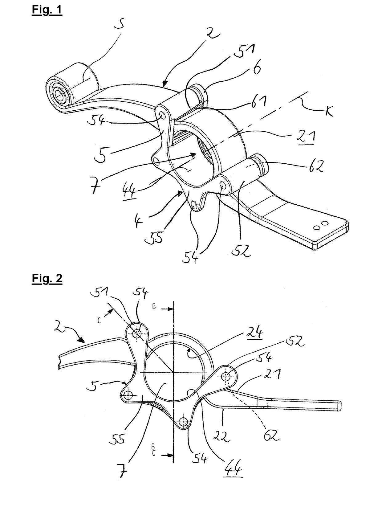
[0028]FIG. 1 is a perspective view of the preferred embodiment of the axle unit according to the invention. In this case, a control arm 2 is provided, which can be pivotally fixed at the first distal end thereof, shown on the left in the drawing, to the frame of a utility vehicle, wherein the control arm 2 can be pivoted in particular about the pivot axis S. At the second distal end thereof which is opposite the first end, the control arm 2 preferably comprises a receiving and fixing region for a spring, in particular an air spring. Furthermore, the control arm 2 has a first side 21, and a second side 22 which is shown as the lower side in the drawing (see reference signs in FIG. 2). A clamping unit 4 can be or is fixed to the control arm 2, wherein in FIG. 1, the clamping unit 4 is shown in the fixed state. The tension elements 8 provided on the clamping unit 4 in this state are not shown in this drawing, but rather are shown for example in FIG. 4. The clamping unit 4 encompasses t...


PUM


Abstract

An axle unit, includes a control arm and a clamping unit that surround a tube region, wherein a first side of the control arm faces away from the tube region, and a second side of the control arm forms a boundary face on the control-arm side of the tube region, wherein the clamping unit can be brought into supporting abutment with the first side of the control arm and has a boundary face on the clamp side, which face defines the tube region, wherein the clamping unit has a first and second clamping parts each having a wedge portion, wherein the wedge portions are formed in such a way that a displacement of the clamping parts substantially in parallel with a clamping axis toward one another results in a narrowing of the tube region transversely to the clamping axis.

Description

BACKGROUND OF THE INVENTION[0001]The present invention relates to an axle unit, in particular to a fastening system for fixing a longitudinal control arm to an axle tube.[0002]Axle units are known from the prior art, in particular fixing axle guides to axle tubes. Various fastening mechanisms have become established here. Thus, firstly a force-fit combination of the longitudinal control arm and the axle tube is produced in that for example U-shaped brackets, which are provided with threads at each of the ends thereof, serve to clamp the axle tube with respect to the control arm. The disadvantage of these U-shaped brackets is the large number of additional components that are required to achieve a sufficiently sturdy seating of the longitudinal control arm on the axle tube and simultaneously prevent rotation of the axle tube as far as possible. Secondly, up to now it has proven expedient to weld the axle tube to the longitudinal control arm, wherein numerous possible weld shapes can ...

Claims


Application Information

Patent Timeline
Patent Type & Authority Applications(United States)
IPC IPC(8): B60B35/00B60G9/00B60G7/00
CPCB60B35/007B60G9/003B60G7/008B60G2200/30B60G2202/152B60G2204/148B60G2204/4306B60G11/113B60G11/465B60G2200/31B60G2202/112B60G2206/15B60G2206/16B60G2206/428B60G2206/7101
Inventor NAGEL, CHRISTOPHER
Owner SAF HOLLAND GMBH
Why Eureka
Try Eureka