
Method of operating a drop-on-demand jetting device

a jetting device and drop-on-demand technology, applied in printing and other directions, can solve the problems of limiting the dotting frequency and the production of printers, different volume and speed of droplets, and reducing the length of the dotting period

Active Publication Date: 2019-01-17
CANON PRODN PRINTING HLDG BV
View PDF1 Cites 2 Cited by
  • Summary
  • Abstract
  • Description
  • Claims
  • Application Information

AI Technical Summary

Benefits of technology

The invention is about a device that controls the pressure wave to create stable jetting conditions. The device uses an over-long waveform that is designed to optimize the pressure wave and shape its time behavior. This allows the device to achieve stable jetting conditions even when there are multiple droplets in the system. The device can also compensate for minor errors in jetting timing by adjusting the speed at which the droplet is jetted out. The overall shape of the waveform does not need to be fixed, as long as the time delay between the pre-fire pulse and the jetting pulse is fixed. This invention improves the quality and efficiency of inkjet printing.

Problems solved by technology

On the other hand, when the print element has been silent in the preceding DOD period, there are no substantial pressure fluctuations in the pressure chamber and the meniscus will be in a “rest” position, and this results in a different volume and speed of the droplet.
This, however, imposes a lower limit on the length of the DOD period and, consequently, limits the DOD frequency and the production of the printer.
Then, however, when the DOD frequency is not constant, the print quality may be compromised by varying time delays between the time when the pre-fire pulse is generated and the time when the jetting pulse is generated.

Method used


Image

  • Method of operating a drop-on-demand jetting device
  • Method of operating a drop-on-demand jetting device
  • Method of operating a drop-on-demand jetting device

Examples


Embodiment Construction

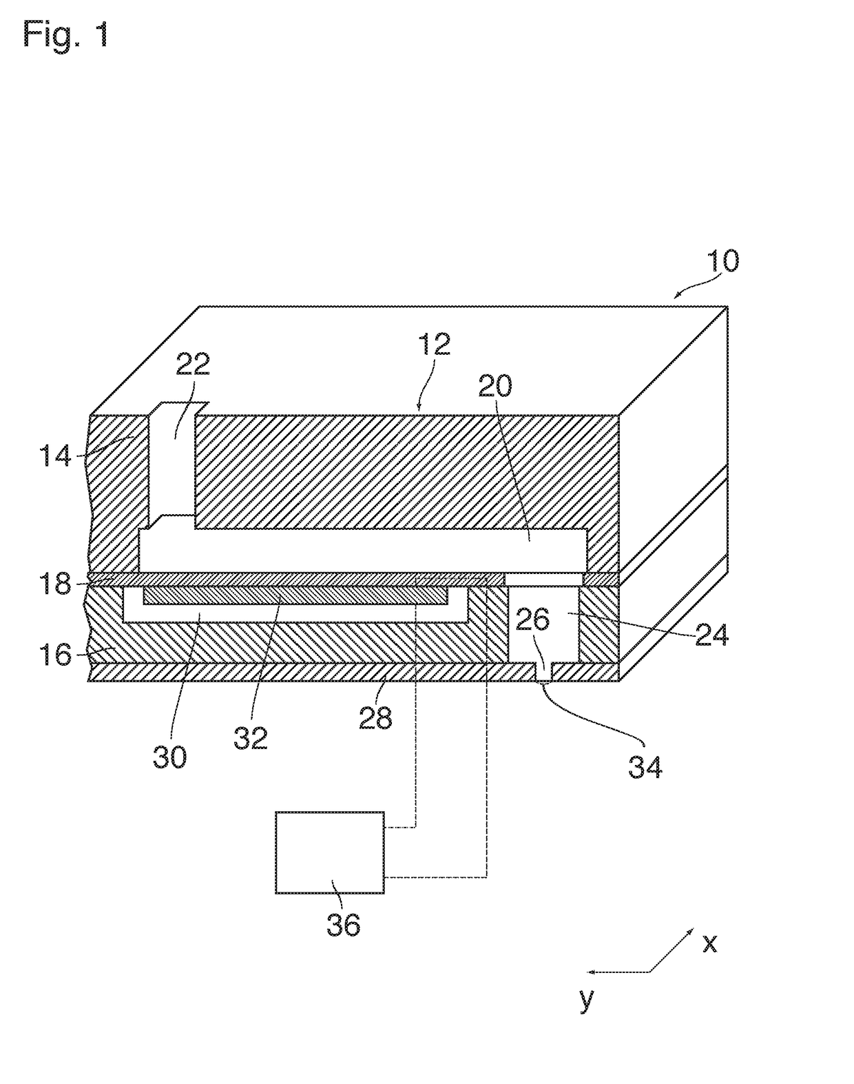
[0025]As an example of a jetting device, FIG. 1 shows a single print element 10 of an ink jet print head. A body 12 of the print head comprises a wafer 14 and a support member 16 that are bonded to opposite sides of a thin flexible membrane 18.

[0026]A recess that forms a pressure chamber 20 is formed in the face of the wafer 14 that engages the membrane 18, i.e. the bottom face in FIG. 1. The pressure chamber 20 has an essentially rectangular shape. An end portion on the left side in FIG. 1 is connected to an ink supply passage 22 that passes through the wafer 14 in thickness direction of the wafer and serves for supplying liquid ink to the pressure chamber 20.

[0027]An opposite end of the pressure chamber 20, on the right side in FIG. 1, is connected, through an opening in the membrane 18, to a chamber 24 that is formed in the support member 16 and opens out into a nozzle 26 that is formed in a nozzle plate 28 constituting the bottom face of the support member 16.

[0028]Adjacent to t...


PUM


Abstract

A method of operating a drop-on demand (DOD) jetting device having a nozzle, a pressure chamber filled with a liquid and connected to the nozzle and an actuator energized by a drive signal, wherein a periodic DOD signal determines whether or not a droplet is jetted out from the nozzle in a given DOD period, and the drive signal has a waveform configured to cause the actuator to excite a pressure wave in the liquid, the method further comprising the steps of a) energizing the actuator with a waveform that has a fixed pattern and extends over a time interval that is longer than the given DOD period; and b) ignoring the DOD signal in at least the first DOD period that follows after said period for which the step a) has been performed.

Description

BACKGROUND OF THE INVENTION1. Field of the Invention[0001]The invention relates to a method of operating a drop-on-demand (DOD) jetting device having a nozzle, a pressure chamber filled with a liquid and connected to the nozzle, and an actuator energized by a drive signal, wherein a periodic DOD signal determines whether or not a droplet is jetted out from the nozzle in a given DOD period, and the drive signal has a waveform configured to cause the actuator to excite a pressure wave in the liquid.[0002]More particularly, the invention relates to a method of operating an ink jet printer and to an ink jet printer that has a circuit configured for executing the invented method.2. Description of the Related Art[0003]US 2016 / 067964 A1 discloses an example of an ink jet printer which can be operated with variable drop-on-demand frequency and, accordingly, with variable DOD period, which permits for example to adapt the length of the DOD periods to varying velocities of the relative moveme...

Claims


Application Information

Patent Timeline
Patent Type & Authority Applications(United States)
IPC IPC(8): B41J2/045
CPCB41J2/04586B41J2/04588B41J2/04536B41J2/04573B41J2/04581B41J2/04598B41J2/04596
Inventor VENNER, CORNELIS W.M.SIMONS, JOHANNES M.M.
Owner CANON PRODN PRINTING HLDG BV
Learn More