Lower vehicle-body structure of automotive vehicle
a vehicle body and lower technology, applied in the direction of superstructure connections, superstructure subunits, vehicle arrangements, etc., can solve the problems of deteriorating ride comfort of passengers, vibration may be transmitted to passengers improperly, and the upper face portion may be easily deformed, so as to improve the rigidity of the surface
- Summary
- Abstract
- Description
- Claims
- Application Information
AI Technical Summary
Benefits of technology
Problems solved by technology
Method used
Image
Examples
embodiment 1
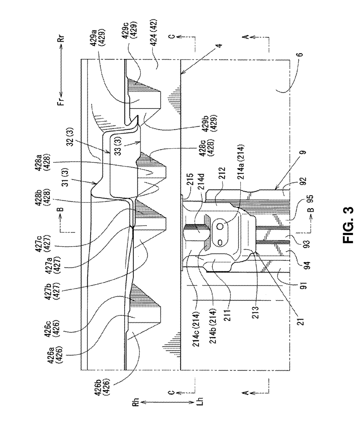
[0045]A lower-vehicle body structure of an automotive vehicle 1 according to a first embodiment will be described specifically referring to FIGS. 1 through 7. Herein, FIG. 1 is a perspective view showing an external appearance of a lower vehicle body of the automotive vehicle 1, FIG. 2 is a perspective view showing an external appearance of the lower vehicle body of the automotive vehicle 1 in a state where a front seat FS is installed, FIG. 3 is a plan view showing an external appearance a part of the lower vehicle body near a center pillar 3, FIG. 4 is a side view showing a side face of the part of the lower vehicle body taken along line A-A of FIG. 3, FIG. 5 is a sectional view taken along line B-B of FIG. 3, FIG. 6 is a perspective view showing an external appearance of a part of the lower vehicle body near a lower portion of the center pillar 3, and FIG. 7 is a sectional view taken along line C-C of FIG. 3.
[0046]In order to clarify illustrations, an external appearance of the f...
embodiment 2
[0138]Next, a second embodiment of the lower vehicle-body structure of the automotive vehicle 1 in which the shape of the side sill inner panel 42 of the side sill 4 and the shape of the first seat-attaching bracket 21 are respectively different from those of the above-described lower vehicle-body structure of the automotive vehicle 1 of the first embodiment will be described specifically referring to FIGS. 8 through 11.
[0139]Herein, FIG. 8 is a perspective view showing an external appearance of the lower vehicle body of the second embodiment, FIG. 9 is a plan view showing a part of the lower vehicle body of the second embodiment near the center pillar 3, FIG. 10 is a side view showing a side face of the part of the lower vehicle body taken along line D-D of FIG. 9, and FIG. 11 is a sectional view taken along line E-E of FIG. 9. The same structures as the first embodiment are denoted by the same reference characters, specific descriptions of which are omitted.
[0140]First, similarly ...
PUM
 Abstract
Description
Claims
Application Information
 - R&D
- Intellectual Property
- Life Sciences
- Materials
- Tech Scout
- Unparalleled Data Quality
- Higher Quality Content
- 60% Fewer Hallucinations
Browse by: Latest US Patents, China's latest patents, Technical Efficacy Thesaurus, Application Domain, Technology Topic, Popular Technical Reports.
© 2025 PatSnap. All rights reserved.Legal|Privacy policy|Modern Slavery Act Transparency Statement|Sitemap|About US| Contact US: help@patsnap.com


