Emergency detection and response system using led-lighting module, and method thereof

a technology of led light and emergency detection, applied in the field of emergency detection and response system using led light, can solve the problems of inefficient disaster response system, affecting the efficiency of the majority of disaster response systems, and the importance of swift initial response after disaster occurren

Inactive Publication Date: 2019-01-03
JPK
View PDF0 Cites 1 Cited by
  • Summary
  • Abstract
  • Description
  • Claims
  • Application Information

AI Technical Summary

Benefits of technology

[0023]According to the above-described present invention, there are following effects.
[0024](1) An emergency detection and response system using an LED-lighting module according to the present invention is configured to detect an emergency situation using an LED-lighting module installed per a certain area in a building and be able to transmit a detection result to a operation unit through a communication network, and provides an effect of enabling a swift response.
[0025](2) An emergency detection and response system using an LED-lighting module according to the present invention provides an effect of swiftly detecting a false alarm error, etc., to transmit an evacuation signal, when receiving the emergency situation detection signal is received by learning, through a cloud platform, an emergency situation detection signal detected by an LED-lighting module, or an operation signal of an operation unit together with the emergency situation detection signal.

Problems solved by technology

In particular, since most cases are such that the golden time for rescue is missed to cause huge losses of human lives, the importance of swift initial response after disaster occurrence is magnified.
However, it is very inefficient in that most of the disaster response systems using the above-described sensors are independent as a stand-alone system, and are independently operated.

Method used


Image

  • Emergency detection and response system using led-lighting module, and method thereof
  • Emergency detection and response system using led-lighting module, and method thereof
  • Emergency detection and response system using led-lighting module, and method thereof

Examples


Embodiment Construction

[0038]The foregoing objects, features and advantages of the invention will be more apparent from the following description. Hereinafter, it will be described about an exemplary embodiment of the present invention in conjunction with the accompanying drawings.

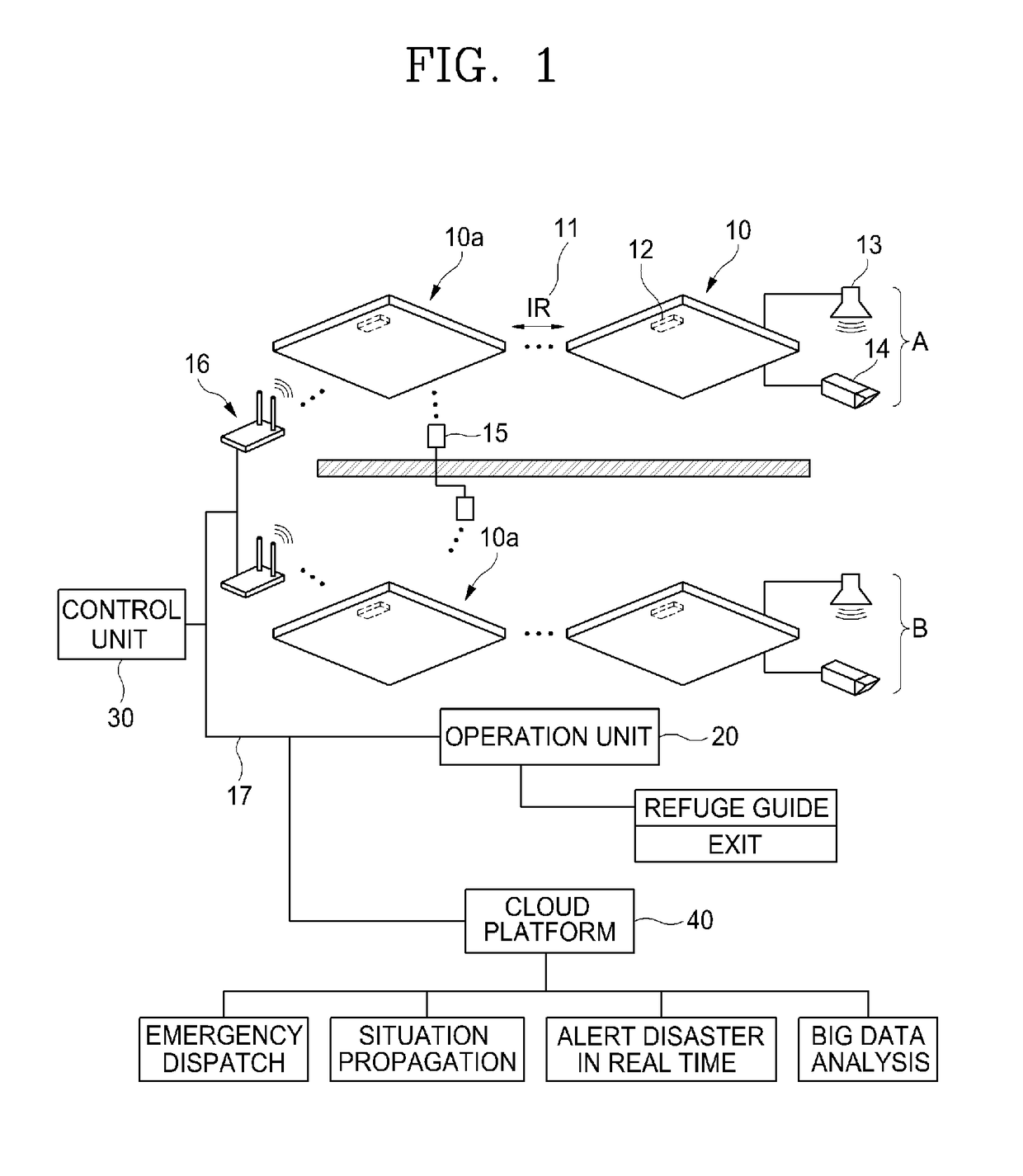
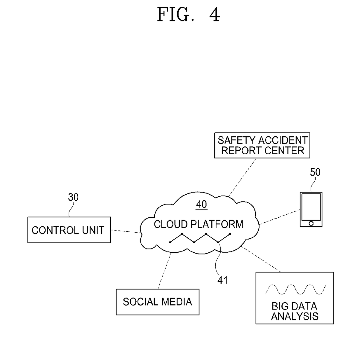
[0039]An emergency detection and response method using an LED-lighting module according to a preferred embodiment of the present invention includes, as shown in FIGS. 1 to 4, an LED-lighting module 10, a communication network 17, a control unit 30, and a cloud platform 40.

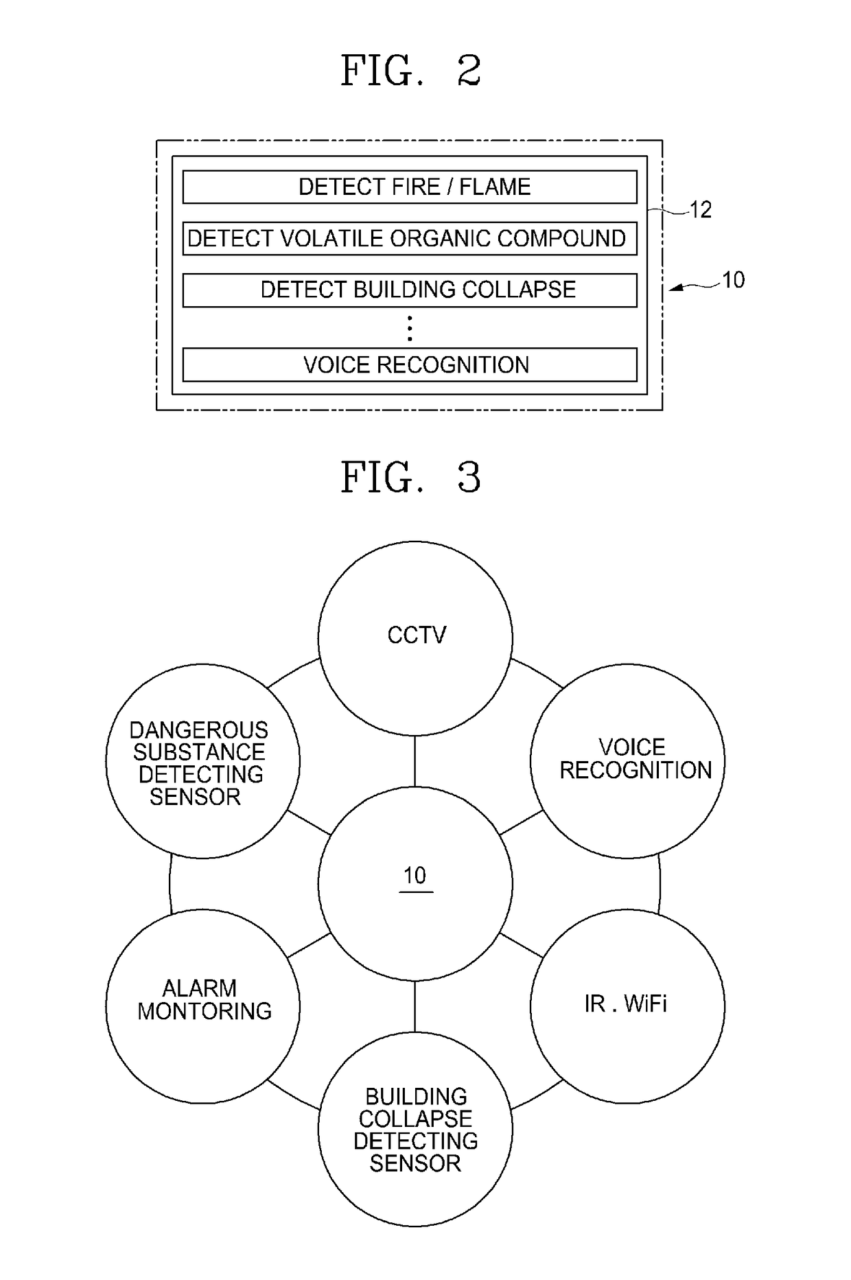
[0040]The LED-lighting module 10 is provided with an emergency detecting sensor 12 for detecting an emergency situation, and a communication sensor 11. The LED-lighting module 10 basically includes a plurality of LED-lighting modules, a power supply device for supplying power to the LED-lighting modules, a light guiding plate for guiding optical sources of the LED-lighting modules to a lower portion, a diffusion plate laminated with the light guiding plate, and...


PUM


Abstract

Disclosed is an emergency detection and response system using LED-lighting modules. The emergency detection and response system using LED-lighting modules, according to the present invention, comprises: a plurality of LED-lighting modules having an emergency sensor for sensing an emergency and a communication sensor; a communication network for, if an emergency is detected by the emergency sensor, receiving emergency detection signals transmitted via the communication sensor and providing the emergency detection signals to an operation unit; a control unit for controlling the LED-lighting modules according to control signals received from the operation unit or a specific emergency detection signal among the emergency detection signals; and a cloud platform for building, as a database, the emergency detection signals received from the communication network or the control signals corresponding to the emergency detection signals and transmitting an early warning signal on the basis of the received signals.

Description

CROSS-REFERENCE TO RELATED APPLICATIONS[0001]This application is a Divisional Application of U.S. patent application Ser. No. 15 / 569,919, which was filed on Oct. 30, 2017, which is a National Stage application of PCT / KR2016 / 004450 filed on Apr. 28, 2016, which claims priority to Korean Patent Application No. 10-2015-0061739, filed on Apr. 30, 2015, the entire contents of which are hereby incorporated by reference.TECHNICAL FIELD[0002]The present invention relates to an emergency detection and response system using an LED-lighting module and a method thereof, and more particularly to an emergency detection and response system using an LED-lighting module capable of grafting a sensor and a network onto an LED-lighting module installed anywhere in a building to detect an emergency situation and respond to the emergency situation within a golden time, and a method thereof.BACKGROUND ART[0003]Recently, a social interest in disaster and safety countermeasure is being heightened as inciden...

Claims


Application Information

Patent Timeline
Patent Type & Authority Applications(United States)
IPC IPC(8): G08B21/02G08B29/18F21V33/00F21V23/04
CPCG08B29/185G08B21/02F21V33/0076F21V23/045F21Y2115/10H05B37/02F21V33/00G08B23/00G08B21/12G08B17/00G08B5/36G08B3/00G08B25/10H05B47/17
Inventor PARK, JONG MINKIM, SEOK TAELEE, HONG MINKOH, YOON II
Owner JPK
Why Eureka
Try Eureka