Device for receiving or emitting/receiving MIMO signals

a technology for receiving or emitting/receiving mimo signals, applied in the field of transmission and the reception of signals, can solve the problems of affecting the global performance of the mimo system, affecting the neighboring devices, and requiring a large amount of processing time, so as to reduce the number of switching schemas in the switching matrix, reduce processing time, and reduce the probability that opposite sectors contribute to the mimo multi-path

Inactive Publication Date: 2016-11-15
MAGNOLIA LICENSING LLC
View PDF25 Cites 0 Cited by
  • Summary
  • Abstract
  • Description
  • Claims
  • Application Information

AI Technical Summary

Benefits of technology

[0024]The use of directive antennae each covering its own angular sector or of a multi-sector antenna enables the number of switching schemas in the switching matrix to be reduced and to make this number less than cnm. Indeed, in a home network context, there is always a main path and therefore a privileged propagation direction. The result is that the probability that opposite sectors contribute to the MIMO multi-path is low. In other words, if a first sector correctly receives MIMO signals, there is a low probability that the opposite sector also correctly receives the MIMO signals. The switching schemes corresponding to these cases can therefore be deleted from the switching matrix,
[0025]According to a specific embodiment, the switching matrix comprises at least the n switching schemes, each selecting m antennae having consecutive angular sectors. In this embodiment, the switching matrix comprises a limited number of switching schemes, namely m switching schemes instead of cnm, resulting in a much reduced processing time for the dynamic management of the antennae.
[0026]According to another embodiment, the switching matrix also comprises the switching schemes, each selecting m antennae having their angular sectors comprised in a set of m+1 consecutive angular sectors, with at most two antennae from among the m selected antennae having opposite angular sectors. In this embodiment, the switching matrix comprises a larger number of switching schemes, which increases the processing time but enables a response to a larger number of multi-path configurations.
[0028]The reduction of the number of switching schemes in the switching matrix (<cnm) enables, in addition to the reduction in the processing time for the dynamic selection of the antennae, the use of a reduced number of switching elements in the switching means and / or the use of switching elements.

Problems solved by technology

In transmission, they also create a lot of interferences affecting neighboring devices.
This is harmful to the global performance of the MIMO system.
This involves quite a long processing time.
This clearly leads to a processing time incompatible with a dynamic management of the antenna device according to the variations in the environment and more specifically in a home network rich in multi-paths.
Moreover, the switching means comprise switching elements leading to losses in the reception of the signals by receiver channels 120 and 121.

Method used


Image

  • Device for receiving or emitting/receiving MIMO signals
  • Device for receiving or emitting/receiving MIMO signals
  • Device for receiving or emitting/receiving MIMO signals

Examples


Embodiment Construction

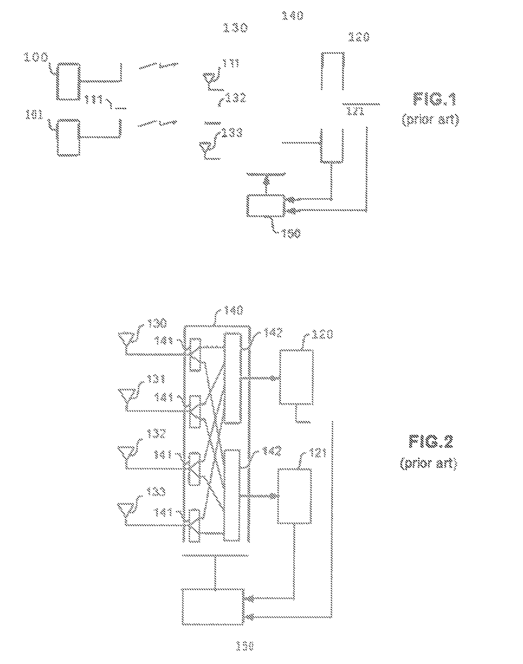
[0050]The invention will be described within the scope of multi-antenna reception device of a MIMO system.

[0051]The invention is more specifically described using different examples of reception devices, namely a reception device for a 2×2 MIMO system of order 2 in reception, a reception device for a 4×4 MIMO system of order 2 in reception and a reception device for a 3×3 MIMO system of order 2 in reception.

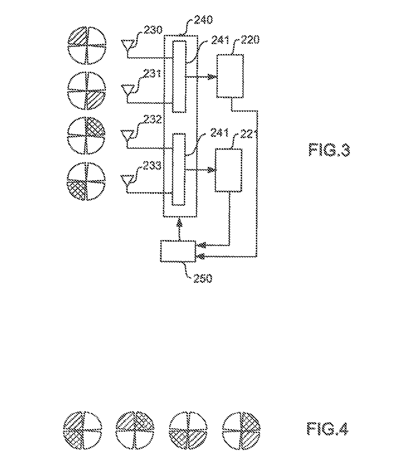
[0052]2×2 MIMO System of Order 2 in Reception

[0053]FIG. 3 shows a reception device for a 2×2 MIMO system of order 2 in reception

[0054]The reception device comprises two receiver channels 220 and 221, four antennae 230 to 233 and switching means 240 for associating with each receiver channel an antenna from among the four antennae 230 to 233. The switching means are controlled by control means 250 selecting a switching schema from a plurality of switching schemes of a switching matrix according to a criterion representing the quality of the reception of the signals by receiver cha...


PUM


Abstract

The invention relates to a device for receiving signals in a MIMO system comprising:m signal receiver channels, where m is greater than 1;an antenna system constituted either by n directive antennae n>m, each antenna being able to receive signals in one of its own angular sectors, the angular sectors of the n antennae essentially not overlapping each other and together thrilling a total angular sector of 360 degrees, or a multi-sector antenna with n angular sectors n>m the n angular sectors essentially not overlapping each other and having a distinct access; andswitching means to associate with each signal receiver channel an antenna from among the n antennae according to a switching schema selected by control means, the switching schema being selected from a plurality of switching schemas of a switching matrix according to a criterion representing the quality of the reception of the signals by said signal receiver channels.

Description

[0001]This application claims the benefit, under 35 U.S.C. §365 of International Application PCT / FR2011 / 052894, filed Dec. 7, 2011, which was published in accordance with PCT Article 21(2) on Jun. 14, 2012 in English and which claims the benefit of French patent application No. 1060241, tiled Dec. 8, 2010.TECHNICAL FIELD[0002]The present invention relates to the transmission and the reception of signals in a MIMO (Multiple Input Multiple Output) type wireless multi-antenna transmission system. The present invention applies more specifically to broadband multimedia home networks.PRIOR ART[0003]The increasing development of digital multimedia devices has given rise to the concept of the home network ensuring the simultaneous distribution of multiple data streams, such as HD (High Definition) video streams, audio streams and computer data streams at any point in the home environment. Such a network, whose structure is dependent on the distribution of rooms within the building (apartmen...

Claims


Application Information

Patent Timeline
Patent Type & Authority Patents(United States)
IPC IPC(8): H01Q1/50H01Q3/24H04B7/04H04B7/08
CPCH01Q1/50H04B7/0408H04B7/0822H04B7/0413
Inventor ROBERT, JEAN-LUCLOUZIR, ALILO HINE TONG, DOMINIQUELE NAOUR, JEAN-YVES
Owner MAGNOLIA LICENSING LLC
Why Eureka
Try Eureka