Shoulder End Range of Motion Improving Device

a shoulder and end-of-shoulder technology, applied in the field of shoulder range of motion therapy, can solve the problems of inconvenient manual methods, patient who has undergone shoulder surgery, and may not be able to return to normal daily activities,

Active Publication Date: 2019-01-03
T REX INVESTMENT INC
View PDF2 Cites 6 Cited by
  • Summary
  • Abstract
  • Description
  • Claims
  • Application Information

AI Technical Summary

Problems solved by technology

For example after shoulder operation, scar tissue may form in shoulder joint tissue (i.e. arthrofibrosis) and as such, mobility of the shoulder may suffer.
A patient who has undergone shoulder surgery may not be able to return to their normal daily activities without rehabilitative therapy.
However, such manual methods are inconvenient because either the therapist or the patient has to travel on a frequent basis, possibly for many months.
As such, shoulder therapy via a physical therapist is time-consuming, inefficient and costly.
However, such training efforts have poor results, however, due to lack of patient and caregiver compliance and insufficient training to replicate the skill of a licensed therapist.
However, current shoulder range of motion therapy machines have various problems.
Common range of motion therapy machines individually are not able to provide end range of motion therapy for all of the above described motions, and as such, multiple different machines are required to be purchased to provide complete therapy.
Further, common range of motion therapy machines are not appropriately configured for active therapy modalities.
Furthermore, common range of motion therapy machines are not configured to record usage data, which may help track progress or check on patient compliance.

Method used


Image

  • Shoulder End Range of Motion Improving Device
  • Shoulder End Range of Motion Improving Device
  • Shoulder End Range of Motion Improving Device

Examples


Embodiment Construction

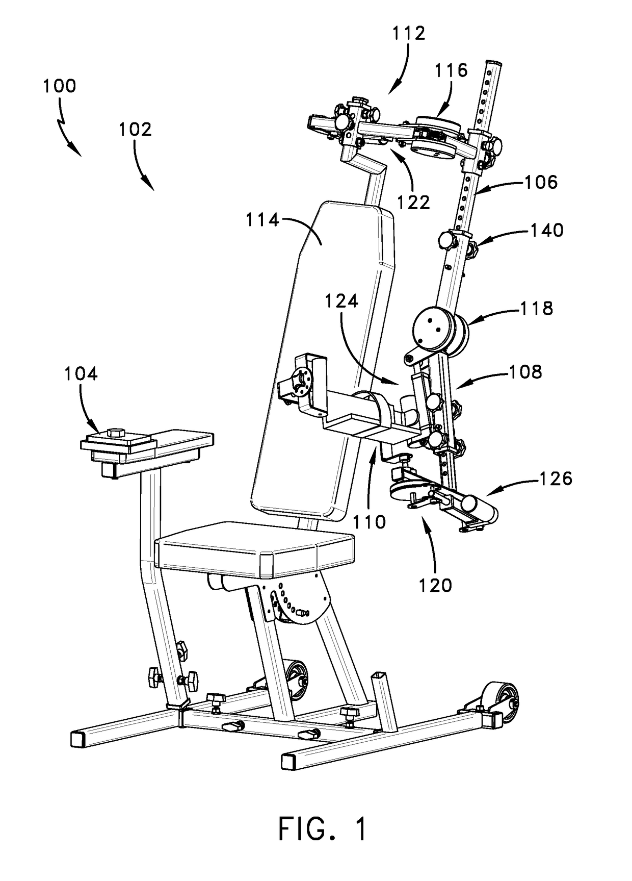
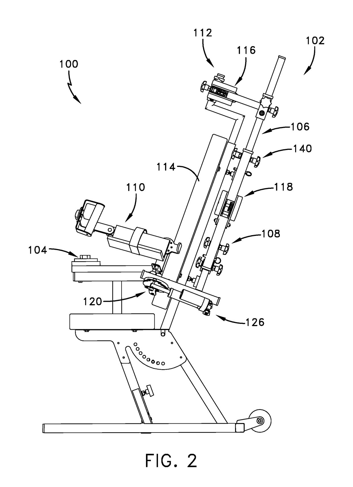
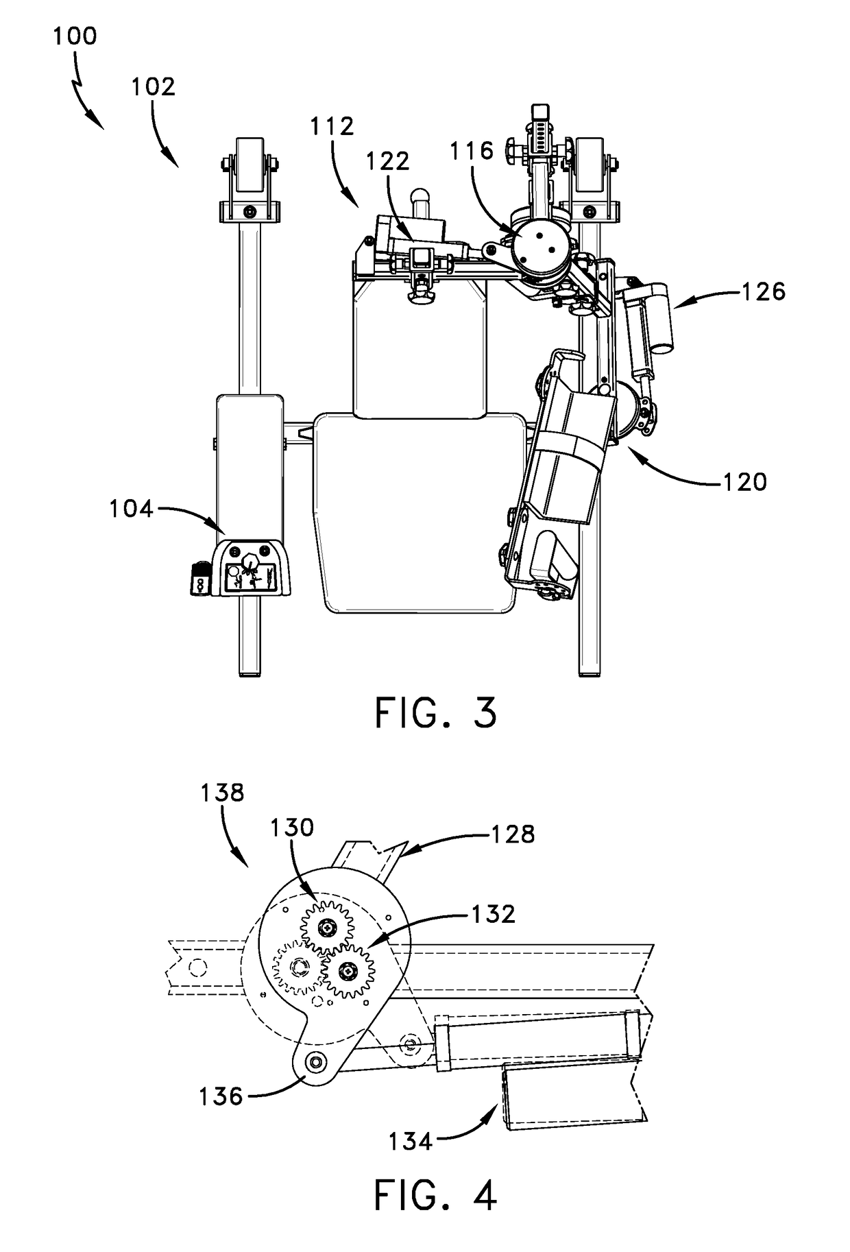
[0036]The following detailed description is merely exemplary in nature and is not intended to limit the described embodiments or the application and uses of the described embodiments. As used herein, the word “exemplary” or “illustrative” means “serving as an example, instance, or illustration.” Any implementation described herein as “exemplary” or “illustrative” is not necessarily to be construed as preferred or advantageous over other implementations. All of the implementations described below are exemplary implementations provided to enable persons skilled in the art to make or use the embodiments of the disclosure and are not intended to limit the scope of the disclosure, which is defined by the claims. Furthermore, there is no intention to be bound by any expressed or implied theory presented in the preceding technical field, background, brief summary or the following detailed description. It is also to be understood that the specific devices and processes illustrated in the at...


PUM


Abstract

Disclosed is an shoulder end range of motion improving device is comprising a linkage, the linkage including, a first link member, a second link member supported on the first link member, the second link member configured for being secured to an arm of a patient and being rotatable about a second link axis for rotating the arm of the patient about a shoulder joint of the patient through an arm range of motion, the second link axis being displaceable into a selectable fixed position and maintaining the fixed position during rotation of the second link member, an actuator for rotating the second link member about the second link axis, and a controller controlling the actuator for selectively rotating the second link member about the second link axis through the arm range of motion.

Description

CROSS-REFERENCE TO RELATED APPLICATIONS[0001]This application is a division of U.S. patent application Ser. No. 14 / 837,280 filed on Aug. 27, 2015 which is a continuation-in-part of U.S. patent application Ser. No. 14 / 730,574, filed on Jun. 4, 2015 now U.S. Pat. No. 9,669,249 issued on Jun. 6, 2017.FIELD OF THE INVENTION[0002]The present invention relates generally to shoulder range of motion therapy, and more particularly to a shoulder range of motion therapy device.BACKGROUND OF THE INVENTION[0003]A human shoulder is a ball and socket joint made up of three bones: the humerus, scapula (i.e. shoulder blade), and clavicle (i.e. collar bone). After certain injuries, surgery or other medical treatments that affect the mobility of the shoulder, it is customary for the patient to be prescribed physical therapy. For example after shoulder operation, scar tissue may form in shoulder joint tissue (i.e. arthrofibrosis) and as such, mobility of the shoulder may suffer. A patient who has under...

Claims


Application Information

Patent Timeline
Patent Type & Authority Applications(United States)
IPC IPC(8): A63B21/00A63B23/12
CPCA63B23/1245A61H2201/0184A63B21/00178A63B21/4047A63B21/4049A63B21/4021A63B21/4017A63B21/00181A63B2225/50A63B2225/20A63B2220/51A63B2220/24A63B2220/17A63B2208/0233A63B2071/0081A63B2071/0072A63B2024/0093A61H2203/0431A61H2201/5097A61H2201/5069A61H2201/5061A61H2201/5046A61H2201/501A61H2201/1676A61H2201/1659A61H2201/1633A61H2201/1616A61H2201/123A61H2201/018A63B24/0087A63B23/1272A63B23/1263A63B23/1254A63B23/03508A63B21/0023A61H1/0281A63B21/4035
Inventor MARTI, EDUARDO M.KAISER, ROBERT T.
Owner T REX INVESTMENT INC
Why Eureka
Try Eureka