An acoustic lens for an ultrasound array

a technology of ultrasound array and acoustic lens, which is applied in the field of acoustic lens for an ultrasound array, can solve the problems of reducing the acoustic performance of the transducer and introducing additional acoustic losses in the cmut array, and achieve the effect of improving the propagation of acoustic waves

Active Publication Date: 2018-12-27
KONINKLJIJKE PHILIPS NV
View PDF0 Cites 3 Cited by
  • Summary
  • Abstract
  • Description
  • Claims
  • Application Information

AI Technical Summary

Benefits of technology

The invention provides an acoustic lens for an ultrasound array that improves the propagation of acoustic waves and is stable chemically and mechanically. It is made using capacitive micromachined transducers.

Problems solved by technology

However, the CMUT possesses different to the PZT mechanism of an electro-acoustical transformation, wherein an interactions between the CMUT membranes and the acoustic materials used for lens may reduce the acoustic performance of the transducer.
It was discovered that traditional filled silicon rubbers (also referred here as room temperature curing rubber or RTV) acoustic lens materials, which are easily cast in place and formed by molding into a desired shape, brought in contact with the CMUT array introduce an additional acoustic losses in the CMUT array in addition to normal frequency dependent attenuation.

Method used


Image

  • An acoustic lens for an ultrasound array
  • An acoustic lens for an ultrasound array
  • An acoustic lens for an ultrasound array

Examples


Embodiment Construction

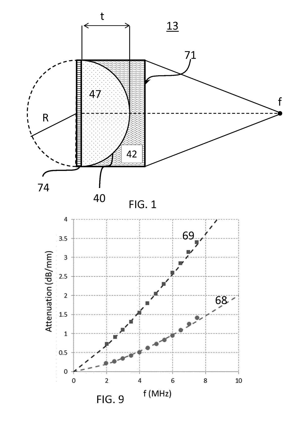
[0036]FIG. 1 shows a principle of constructing a converging acoustic lens 13. The lens 13 is coupled to a source of the acoustic waves—an array of the capacitive ultrasound transducers 74. Further, the acoustic lens comprises a first layer 47 forming an inner layer, which is in an acoustic contact with the CMUT array, and a second layer 42 forming an outer layer of the lens. The first layer 47 has an inner surface arranged to face the array and outer convex shaped surface 40 arranged to oppose the inner surface of the first layer. The second layer coupled to the outer surface of the first layer may be forming an outer surface 71 of the acoustic lens 13. The outer surface is intended to face a patient 201 or a body to be examined by the ultrasound imaging system 202 (illustrated in FIG. 12).

[0037]When a speed of the sound or acoustic wave velocity varies from the first layer to the second layer of the acoustic lens a converging or diverging lens can be constructed. To illustrate in t...


PUM


Abstract

An acoustic lens suitable for a CMUT array (74) is provided. The acoustic lens comprising: a first layer (47) comprising a thermoset elastomer having a polymeric material selected from hydrocarbons, wherein the first layer has an inner surface (72) arranged to face the array and an outer convex shaped surface (40) arranged to oppose the inner surface; and a second layer (42) coupled to the outer surface of the first layer and comprising thermoplastic polymer polymethylpentene and an elastomer selected from the polyolefin family (POE) blended therein, wherein the outer layer located at the outer surface of the acoustic window layer, wherein the first layer has a first acoustic wave velocity (v1) and the second layer has a second acoustic wave velocity (v2), said second velocity is larger than the first acoustic wave velocity.

Description

FIELD OF THE INVENTION[0001]The invention relates to an acoustic lens for an ultrasound array of capacitive micromachined transducers. The invention further relates an ultrasound probe comprising such an acoustic lens.BACKGROUND OF THE INVENTION[0002]Recent progress in semiconductor technology resulted in the development of capacitive micro-machined ultrasound transducers (CMUT). These transducers are considered to be potential candidates to replace the conventional piezoelectric based ultrasound transducers (PZT). A CMUT transducer cell comprises a cavity with a movable mechanical part also called a membrane and a pair of electrodes separated by the cavity. When receiving ultrasound waves, ultrasound waves cause the membrane to move or vibrate and change the capacitance between the electrodes which can be detected. Thereby the ultrasound waves are transformed into a corresponding electrical signal. Conversely, an electrical signal applied to the electrodes causes the membrane to mo...

Claims


Application Information

Patent Timeline
IPC IPC(8): G10K11/30B06B1/02A61B8/00G01N29/24G01N29/22
CPCG10K11/30B06B1/0292A61B8/4444A61B8/4494G01N29/2406G01N29/221
Inventor DIRKSEN, PETERSHULEPOV, SERGEIHAKKENS, FRANCISCUS JOHANNES GERARDUSTIMMERMANS, PETRUS HENRICUS MARIABECKERS, LUCAS JOHANNES ANNA MARIA
Owner KONINKLJIJKE PHILIPS NV
Why Eureka
Try Eureka