Eureka AIR delivers breakthrough ideas for toughest innovation challenges, trusted by R&D personnel around the world.

Normalized status variables for vibration management of drill strings

a technology of status variables and vibration management, which is applied in the field of normalized status variables for vibration management of drill strings, can solve problems such as severe oscillations and damage to drill string components

Active Publication Date: 2018-12-27
BAKER HUGHES INC
View PDF5 Cites 28 Cited by
  • Summary
  • Abstract
  • Description
  • Claims
  • Application Information

AI Technical Summary

Benefits of technology

The patent is a method and apparatus for adjusting drilling parameters of a drill string by using a mathematical model, sensing the modes of the drill string, and calculating the oscillation amplitude at different positions in the drill string to adjust the drilling parameters. The technical effect is to improve the stability and efficiency of drilling operations by optimizing the drilling parameters based on the mathematical model and the sensor data.

Problems solved by technology

Unfortunately, rotation of the drill string and the interaction of the drill bit with the formation rock can lead to severe oscillations that can damage the drill string components.

Method used


Image

  • Normalized status variables for vibration management of drill strings
  • Normalized status variables for vibration management of drill strings
  • Normalized status variables for vibration management of drill strings

Examples


embodiment 1

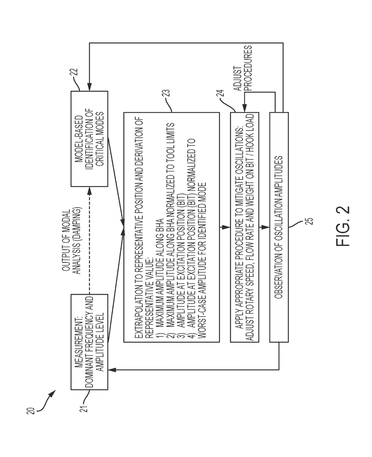
[0041] A method for adjusting a drilling parameter of a drill string, the method comprising: determining with a processor one or more modes of the drill string using a mathematical model; sensing with a sensor at least one of a first oscillation amplitude at a first position in the drill string and an oscillation parameter of the drill string, different from the first oscillation amplitude, at the first position or a second position in the drill string to provide at least one of measured first oscillation amplitude data and measured oscillation parameter data; identifying with the processor a mode of the drill string using the one or more determined modes and a stability criterion and at least one of the measured first oscillation amplitude data and the measured oscillation parameter data; calculating with the processor an oscillation amplitude at a position of interest in the drill string using the identified mode and at least one of the measured first oscillation amplitude data, t...

embodiment 2

[0042] The method according to any prior embodiment, wherein the oscillation parameter of the drill string, different from the first oscillation amplitude is at least one of a second oscillation amplitude at a second position in the drill string, a rotary speed of a rock cutting structure in the drill string, and an oscillation frequency at the first position in the drill string.

embodiment 3

[0043] The method according to any prior embodiment, wherein the rock cutting structure is at least one of a drill bit, a hole opener, and a reamer.


PUM


Abstract

A method for adjusting a drilling parameter of a drill string includes: determining one or more modes of the drill string; sensing a first oscillation amplitude at a first position in the drill string and / or an oscillation parameter of the drill string at the first position or a second position to provide measured first oscillation amplitude data and / or measured oscillation parameter data; identifying a mode of the drill string using one or more determined modes and a stability criterion and at least one of the measured first oscillation amplitude data and the measured oscillation parameter data; calculating an oscillation amplitude at a position of interest in the drill string using the identified mode and at least one of the measured first oscillation amplitude data, the measured oscillation parameter data and the stability criterion; and adjusting the drilling parameter in response to the calculated oscillation amplitude at the position of interest.

Description

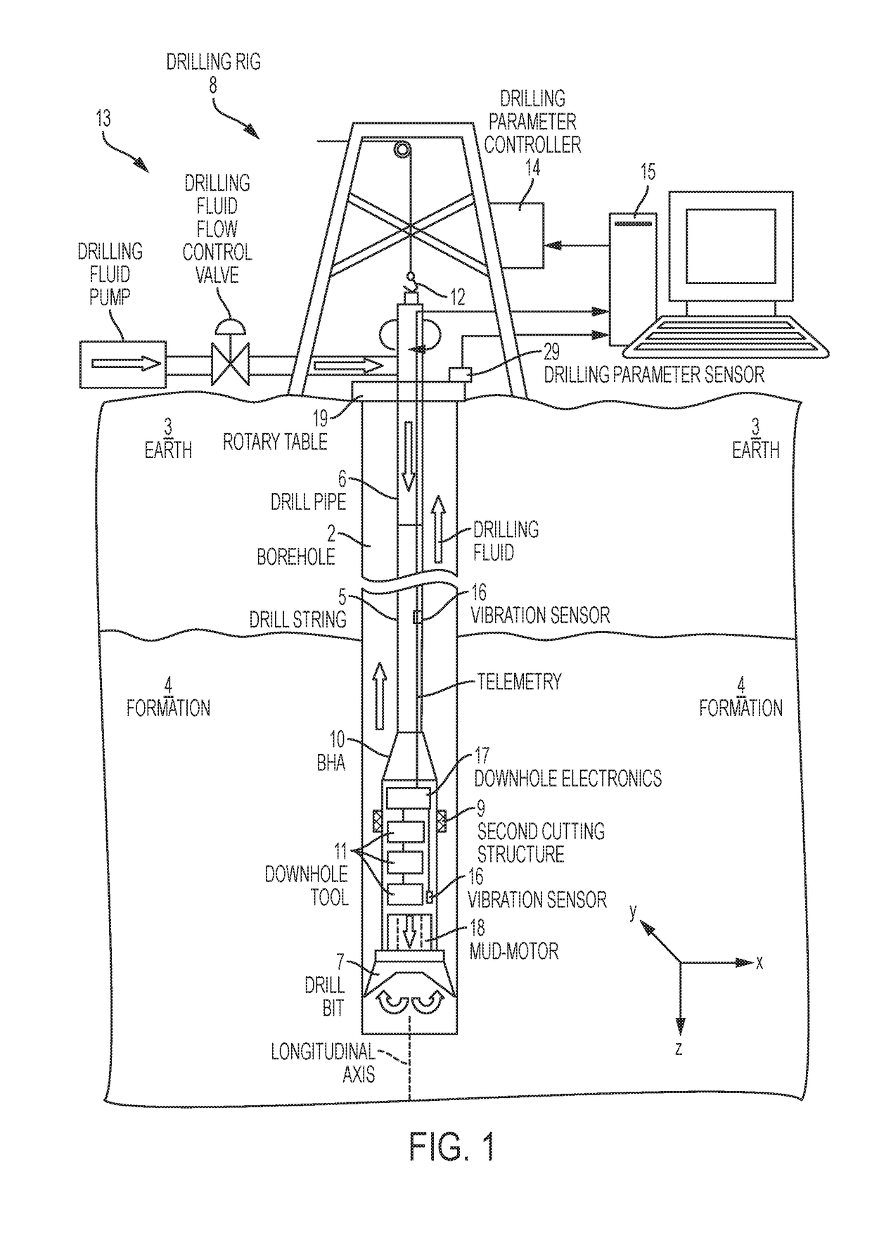
BACKGROUND[0001]Boreholes are drilled into earth formations for various purposes such as hydrocarbon production, geothermal production, and carbon dioxide sequestration. Typically, a borehole is drilled using a drill string having a drill bit. The drill string is rotated at the surface of the earth in order to rotate the drill bit, which cuts or disintegrates formation rock to form the borehole. Unfortunately, rotation of the drill string and the interaction of the drill bit with the formation rock can lead to severe oscillations that can damage the drill string components. Hence, it would be appreciated in the drilling industry if methods and apparatuses were developed that could limit severe oscillations of drill strings while boreholes are being drilled.BRIEF SUMMARY[0002]Disclosed is a method for adjusting a drilling parameter of a drill string. The method includes: determining with a processor one or more modes of the drill string using a mathematical model; sensing with a sens...

Claims


Application Information

Patent Timeline
Patent Type & Authority Applications(United States)
IPC IPC(8): E21B44/00E21B47/12
CPCE21B44/00E21B47/12E21B44/005E21B47/095E21B44/08
Inventor HOHL, ANDREASHERBIG, CHRISTIANOUESLATI, HATEMRECKMANN, HANNONEUBERT, MICHAEL
Owner BAKER HUGHES INC
Why Eureka
Eureka Blog
Learn More