Terminal connecting structure
- Summary
- Abstract
- Description
- Claims
- Application Information
AI Technical Summary
Benefits of technology
Problems solved by technology
Method used
Image
Examples
first embodiment
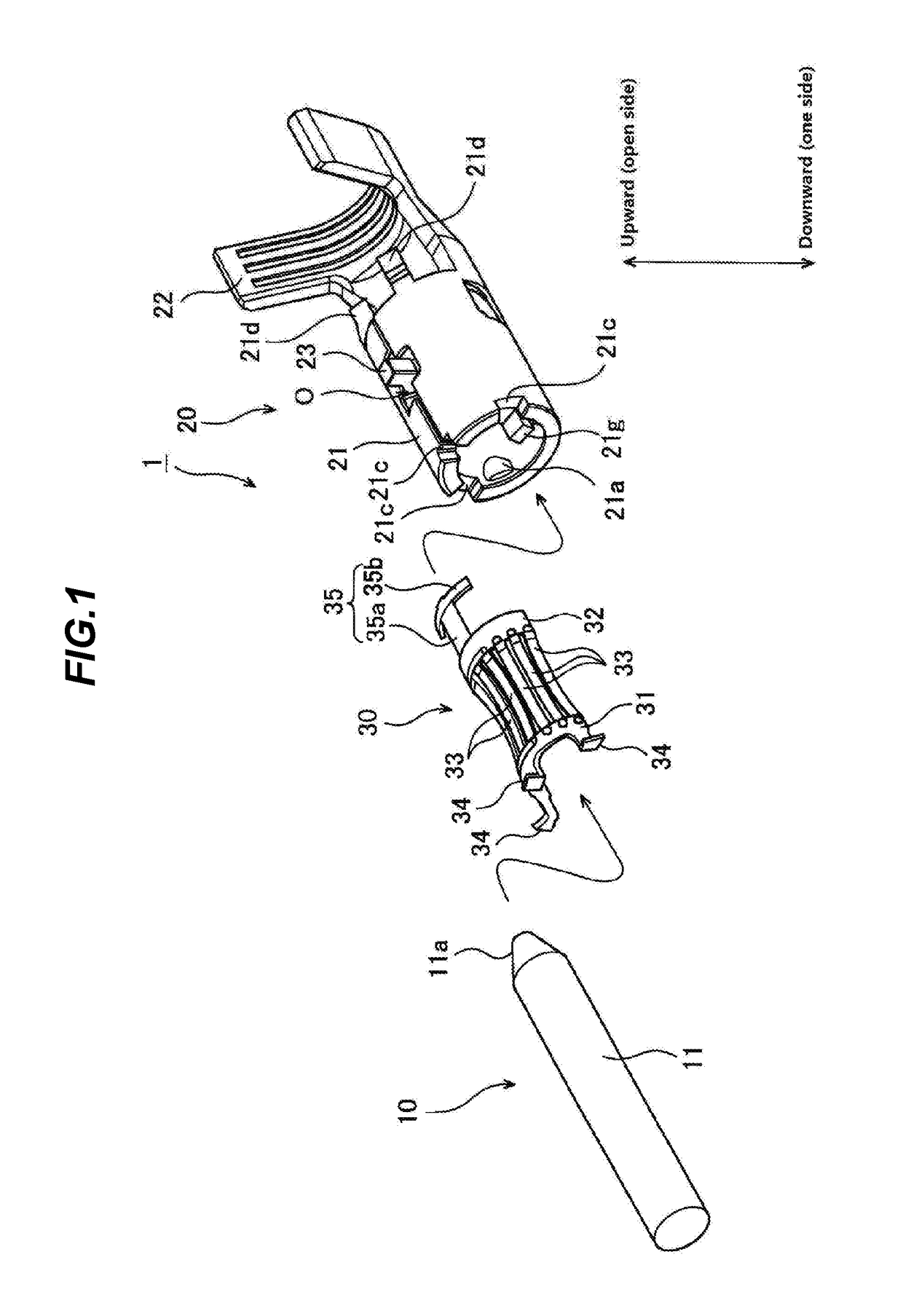
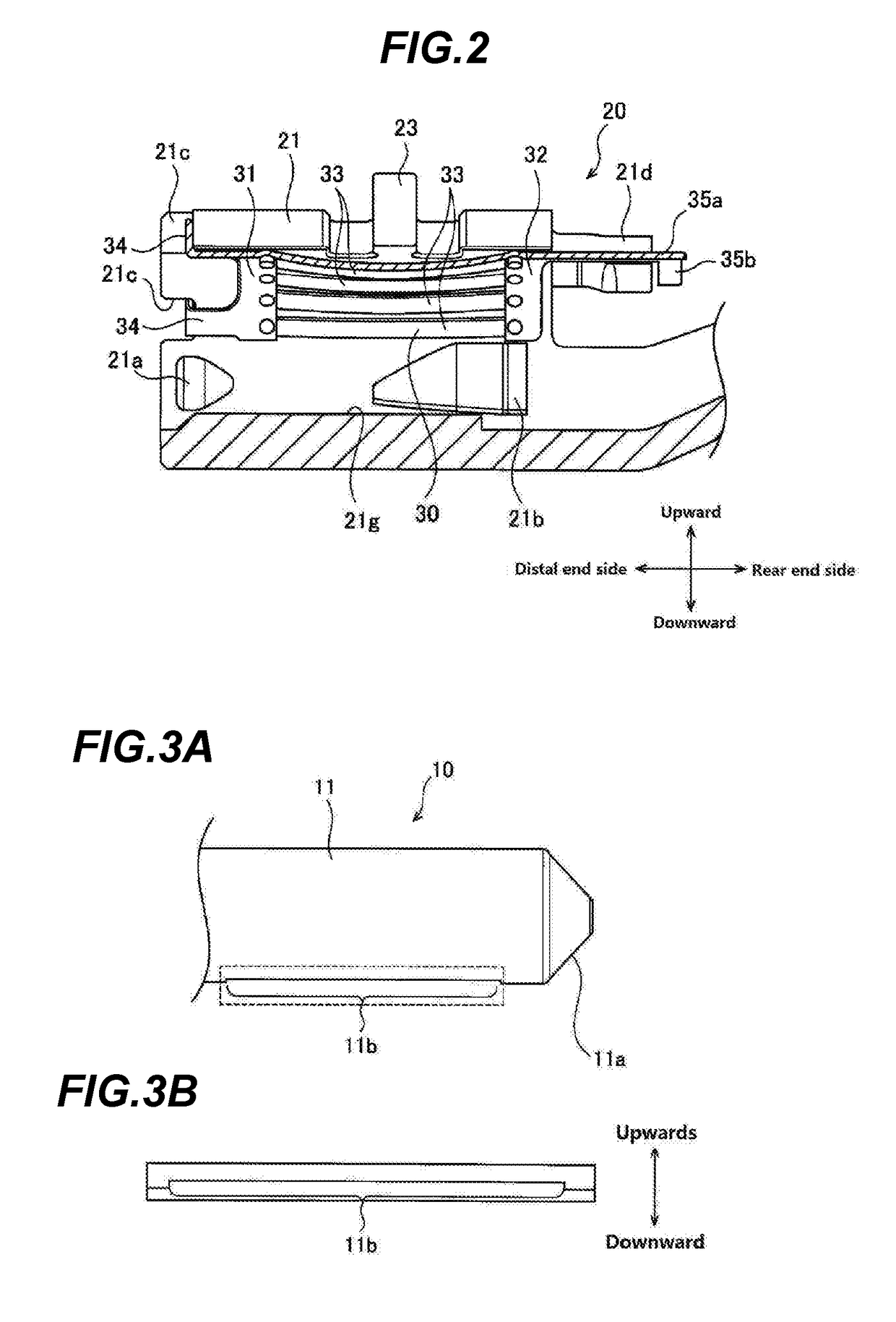
[0057]In this way, with the terminal connecting structure 1 since the projecting portion 21g is formed to prevent the rod-shaped portion 11 from coming into contact with the indented portions 21a, 21b in the inserting process of the male terminal 10, the rod-shaped portion 11 does not come into contact with the indented portions 21a, 21b, thereby preventing the inserting force from being enhanced by the indented portions 21a, 21b. Additionally, since the projecting portion 21g is provided at the portion that constitutes the central portion C on the one side of the inner wall of the cylindrical portion 21, the projecting portion 21g is made to lie square to the spring reaction force to bear it, whereby the inserting force would be reduced when compared with the inserting force enhanced by the indented portions 21a, 21b. In addition, since the cut-out portion 11b is formed so that the projecting portion 21g fits therein to cause the rod-shaped portion 11 to be brought into contact wi...
second embodiment
[0069]In this way, with the terminal connecting structure 1 the movement of the rod-shaped portion 11 would preferably be restricted after the fitment of the rod-shaped portion 11 in the cylindrical portion 21 while reducing the inserting force required when the male terminal 10 is inserted into the female terminal 20. Additionally, the substantially cylindrical rod-shaped portion 11 would be inserted with the reduced inserting force while being prevented from deflecting much in an axial direction. Further, the assembling property of the elastic member 30 to the female terminal 20 would be enhanced.
[0070]Next, a third embodiment will be described. A terminal connecting structure according to the third embodiment is similar to that of the first embodiment but differs partially in configuration (the configurations of a male terminal 10 and a female terminal 20). Hereinafter, features that differ from the first embodiment will be described.
[0071]FIG. 12 is a sectional view resulting w...
third embodiment
[0072]As FIG. 12 shows, in the third embodiment, a female terminal 20 includes a through hole 24 on a distal end side of a lower central portion C inside a cylindrical portion 21. The through hole 24 is intended for a projection to fit in it to prevent the female terminal 20 accommodated in a connector from being dislocated from the connector.
[0073]A projecting portion 21g in the third embodiment is intended to prevent a rod-shaped portion 11 from being brought into contact with a plurality of indented portions 21a, 21b in an inserting process of the rod-shaped portion 11 into the cylindrical portion 21, as with the projecting portion 21g described in the first embodiment. However, the projecting portion 21g of the third embodiment has a length that is shorter than that of the projecting portion 21g of the first embodiment. Namely, the projecting portion 21g of the third embodiment is provided at a portion that lies further towards a distal end side of the female terminal 20 than th...
PUM
 Abstract
Description
Claims
Application Information
 - R&D
- Intellectual Property
- Life Sciences
- Materials
- Tech Scout
- Unparalleled Data Quality
- Higher Quality Content
- 60% Fewer Hallucinations
Browse by: Latest US Patents, China's latest patents, Technical Efficacy Thesaurus, Application Domain, Technology Topic, Popular Technical Reports.
© 2025 PatSnap. All rights reserved.Legal|Privacy policy|Modern Slavery Act Transparency Statement|Sitemap|About US| Contact US: help@patsnap.com


