
Adjustment structure of bridle

Active Publication Date: 2018-12-20
ACER INC
View PDF0 Cites 10 Cited by
  • Summary
  • Abstract
  • Description
  • Claims
  • Application Information

AI Technical Summary

Benefits of technology

The patent provides a way for a user to adjust a bridle using a knob and rotating shaft. The movement of the knob along the shaft can engage or disengage certain parts of the bridle, allowing for easy adjustment. The technical effect is that this makes it easier for users to quickly and easily adjust the bridle for their unique needs.

Problems solved by technology

Furthermore, the movement of the knob along the rotating shaft can further cause the third ring gear to be engaged with or not to be engaged with the second ring gear.

Method used


Image

  • Adjustment structure of bridle
  • Adjustment structure of bridle
  • Adjustment structure of bridle

Examples


Embodiment Construction

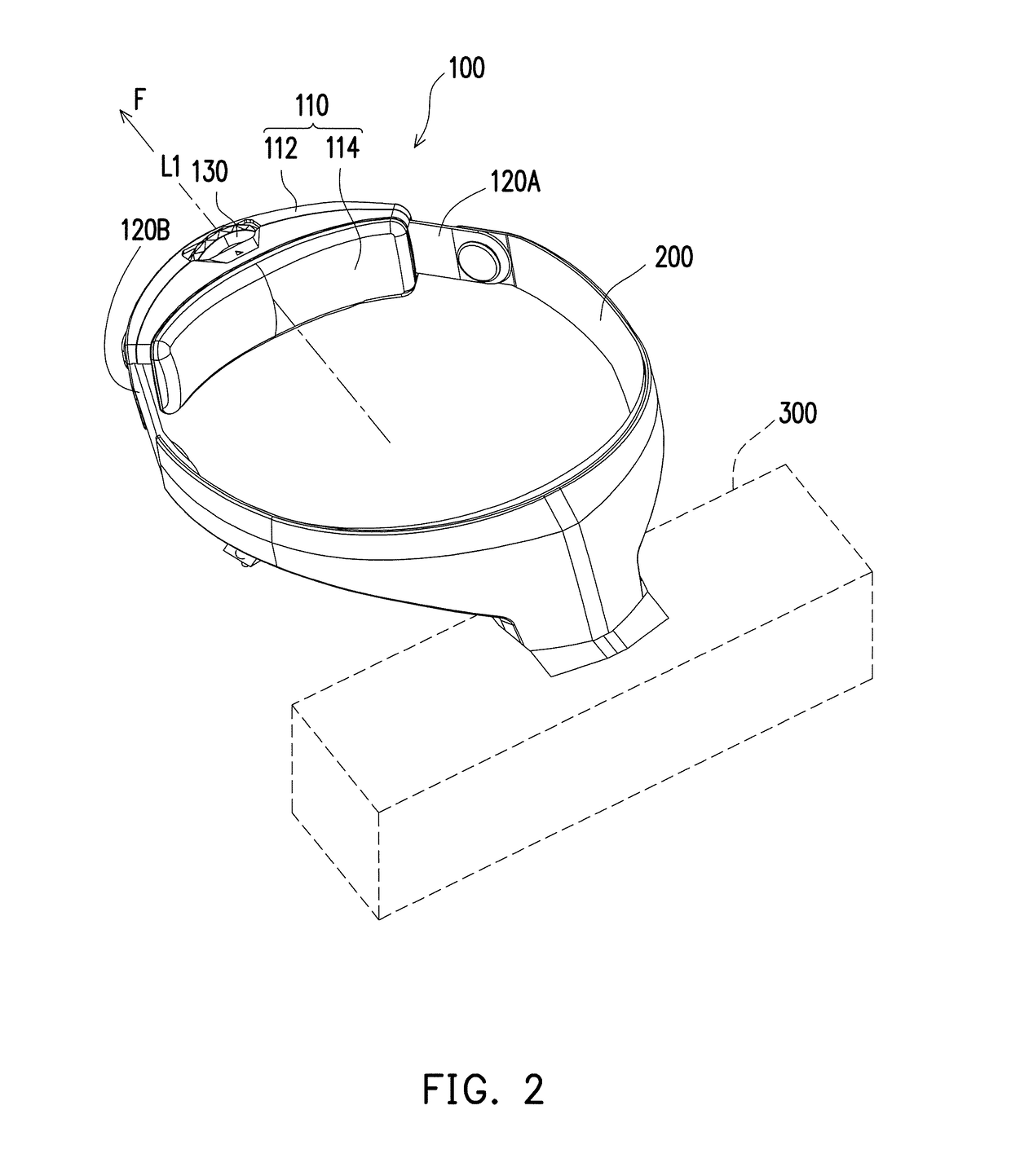
[0017]FIG. 1 is a schematic view illustrating an adjustment structure of a bridle according to an embodiment of the disclosure. FIG. 2 is a schematic view illustrating the adjustment structure of bridle of FIG. 1 in another state. Referring to both of FIG. 1 and FIG. 2, in the embodiment, an adjustment structure of bridle 100 includes bridles 120A and 120B, a belt body 200, a housing 110 and a knob 130. Here, the belt body 200 is, for example, a head-mounted ring which is connected to an object 300 at a position away from the bridles 120A and 120B. It is adaptable for a user to put the belt body 200 on the head so as to perform related actions on the object 300. The object 300 is, for example, an electronic device or a mask such as a display and the like; the disclosure provides no limitation to the form of the object. Here, the bridles 120A and 120B are respectively connected to two opposite ends of the belt body 200 and overlap each other in the housing 110. As shown in FIG. 1 and...


PUM


Abstract

An adjustment structure of bridle including a bridle, rotating shaft, and a knob is provided. The bridle has a rack. The rotating shaft has a first ring gear and a second ring gear both around an axis, wherein the first ring gear is coupled to the rack, such that the rotating shaft moves along the bridle by rotating about the axis itself The knob is rotated about the axis and moved along the axis to be movably coupled to the rotating shaft. The knob has a third ring gear to be engaged with or released from the second ring gear by the knob moving along the axis. When the third ring gear is engaged with the second ring gear, the knob is forced to drive the rotating shaft to rotate about the axis.

Description

CROSS-REFERENCE TO RELATED APPLICATION[0001]This application claims the priority benefit of Taiwan application serial no. 106120506, filed on Jun. 20, 2017. The entirety of the above-mentioned patent application is hereby incorporated by reference herein and made a part of this specification.BACKGROUNDTechnical Field[0002]The disclosure is related to an adjustment structure of bridle.Description of Related Art[0003]In terms of a wearable object such as a face mask, a mask, clothing, a backpack or even an electronic device, it is a common means to use a bridle to tie the wearable object to a user for ease of use or to prevent the wearable object from falling. To adapt to the shape of various wearable object as well as the position or use of the wearable object to be worn on the user, different bridle structures have also been developed correspondingly.[0004]With rapid advancement of technologies, a head-mounted device integrated with an electronic module as a product have been develo...

Claims


Application Information

Patent Timeline
IPC IPC(8): G02B27/01A42B1/24G06F1/16G02B27/02
CPCG02B27/0176A42B1/245G02B2027/0159G02B27/02G02B2027/0154G06F1/163A42B3/145A45F5/00A45F2200/0516A45F2200/0525A45F2200/0533B68B1/04
Inventor LIN, LILIN, KER-WEITU, CHIH-KAICHEN, CHUN-TACHEN, CHUN-YU
Owner ACER INC
Learn More