Method and device for a medical image analysis

a medical image and analysis technology, applied in the field of radiology, can solve the problems of not being able to complete the tumor characterization, imaging is noninvasive, and the voltage of the ray tube is usually 100-120 kvp, and achieve the effect of precise assessment of the subject's range of interes

Pending Publication Date: 2018-12-20
KONINKLJIJKE PHILIPS NV
View PDF0 Cites 13 Cited by
  • Summary
  • Abstract
  • Description
  • Claims
  • Application Information

AI Technical Summary

Benefits of technology

The patent describes a method to improve the performance of medical imaging processing by repeating the steps of the method twice. This increases the speed of processing. The method uses a higher resolution in the second image, which provides more precise information about the subject being imaged. The higher resolution scan is preferably a high dose scan, which targets only the region of interest with a high dose while the rest of the zone receives a low dose. This optimizes the scan parameters and allows for high-quality imaging with reduced patient dose.

Problems solved by technology

However, as tumors are spatially and temporally heterogeneous, these techniques are limited.
They require biopsies or invasive surgeries to extract and analyze what are generally small portions of tumor tissue, which do not allow for a complete characterization of the tumor.
Further, imaging is noninvasive and is already often repeated during treatment in routine practice.
The x-ray tube voltage is usually 100-120 kVp, which is not always optimal for the highest low-contrast resolution: e.g. sometimes 80 kVp will be better suited in that respect, although such voltage would increase the noise.
Therefore, there is a practical problem due to the overall required high dose, to perform high definition scan protocols in cases of large tumor areas or tumors with multiple focal points or spread metastasizes, or even when it is not clear from a standard scan which region is the optimal candidate for Radiomics analysis.

Method used


Image

  • Method and device for a medical image analysis
  • Method and device for a medical image analysis
  • Method and device for a medical image analysis

Examples


Embodiment Construction

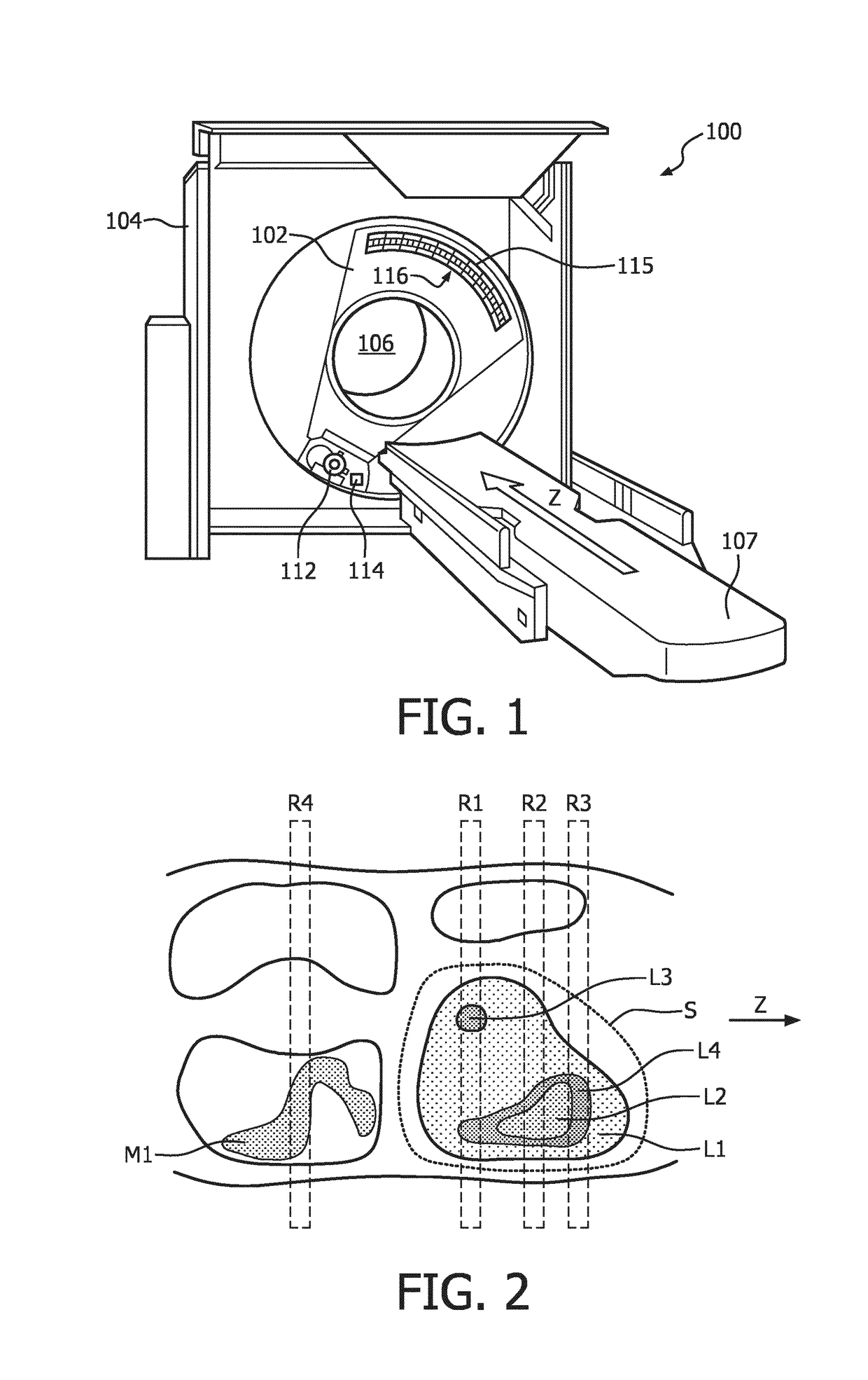
[0109]FIG. 1 schematically illustrates an example imaging system 100, such as a computed tomography (CT) scanner. The imaging system 100 includes a rotating gantry 102 and a stationary gantry 104. The rotating gantry 102 is rotatably supported by the stationary gantry 104. The rotating gantry 102 is configured to rotate around an examination region 106 about a longitudinal or z-axis. The imaging system 100 further includes a subject support 107 that supports a subject or object in the examination region 106 before, during and / or after scanning. The subject support 107 can also be used to load and / or unload the subject or object into or from the examination region 106. The imaging system 100 further includes a radiation source 112, such as an x-ray tube, that is rotatably supported by the rotating gantry 102. The radiation source 112 rotates with the rotating gantry 102 around the examination region 106 and is configured to generate and emit radiation that traverses the examination r...


PUM


Abstract

The invention relates to a method for a medical image analysis, comprising the steps: Performing a first CT scan of a region of interest of a subject resulting in a first image with a first resolution; Applying a medical image processing method to the first image resulting in first values representing a first analysis of the region of interest of the subject; Determining a range of interest of the subject based on the first values; Performing a second CT scan of the range of interest of the subject resulting in a second image with a second resolution, wherein the second resolution is higher than the first resolution; and Applying the medical imaging processing method to the second image resulting in second values representing a second analysis of the range of interest of the subject. Further, the invention relates to a system for medical image analysis.

Description

[0001]The present invention relates to a method and a device for a medical image analysis. The invention further relates to a respective computer program element and a respective computer readable medium.BACKGROUND OF THE INVENTION[0002]The field of ‘Radiomics’ usually refers to the extraction and analysis of large amounts of information from medical images using advanced quantitative feature analysis, for example in the context of comprehensive quantification of tumor phenotypes. The image feature space, corresponding to the relevant selected regions (such as a segmented tumor), is constructed using automatically extracted data-characterization algorithms.[0003]A central hypothesis in Radiomics, that has been recently validated in clinical studies, is that the underlying biological characteristics of aggressive tumors could translate into macroscopic heterogeneous tumor metabolism and anatomy. Some studies reveal that a prognostic Radiomic signature, related to tumor tissue heterog...

Claims


Application Information

Patent Timeline
IPC IPC(8): A61B6/00A61B6/03G06K9/46G06K9/62G06T7/00G06T7/12G06T7/13G06T7/174G06V10/143G06V10/25
CPCA61B6/469A61B6/032A61B6/54G06K9/46G06K9/6267G06T7/0012G06T7/12G06T7/13G06T7/174A61B6/5217G06T2207/10081G06T2207/30096A61B6/488A61B6/545G06T2207/20104G06T2207/30056G06T2207/20076G06T7/11G16H30/40G16H40/60A61B6/0487G06V10/143G06V10/25G06V2201/03G06F18/24G16H50/30
Inventor CARMI, RAZ
Owner KONINKLJIJKE PHILIPS NV
Why Eureka
Try Eureka