
Ltps array substrate and method for manufacturing the same

a technology of array substrate and low temperature polysilicon, which is applied in the direction of device details, instruments, and piezoelectric/electrostrictive device details, etc., can solve the problems of increasing the cost of manufacturing display panels, reducing the sensitivity of touch control signals, and generating interference among touch control signals. , to achieve the effect of reducing the sensitivity of sensing touch pressure, increasing the weight and thickness of the panel, and high quality

Active Publication Date: 2018-12-13
WUHAN CHINA STAR OPTOELECTRONICS TECH CO LTD
View PDF0 Cites 12 Cited by
  • Summary
  • Abstract
  • Description
  • Claims
  • Application Information

AI Technical Summary

Benefits of technology

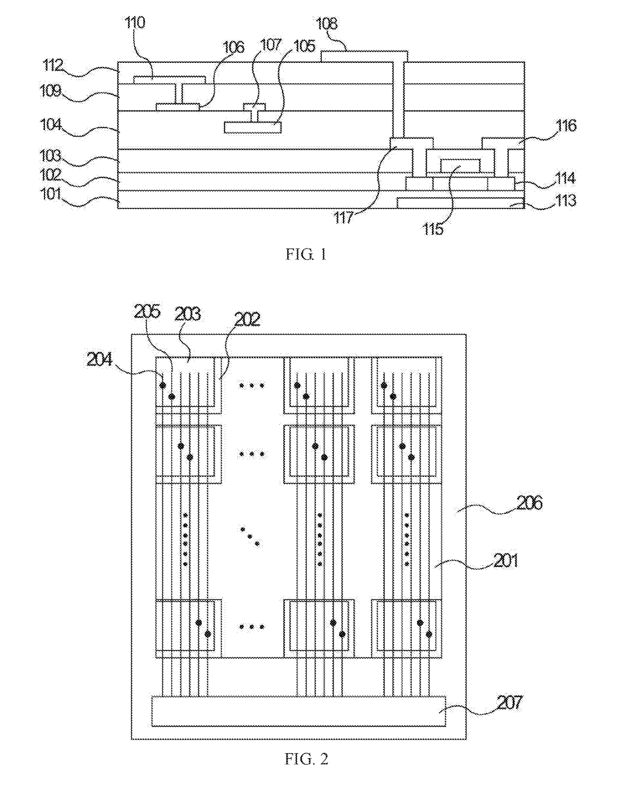
The present patent provides an LTPS array substrate that integrates pressure sensors for touch pressure control. This substrate improves sensitivity while avoiding interference between touch control signals. Compared to conventionally-used add-on type of touch pressure control panel, the present invention is more efficient and compact, and solves issues such as lower sensitivity and increased weight and thickness. It provides a built-in type of touch pressure control panel with high quality.

Problems solved by technology

However, the touch control layer is integrated within the display panel, and it generates interference among touch control signals.
But, because there is an air layer at the upper side and the lower side of the pressure sensors, this makes lower sensitivity of touch pressure.
However, addition of attaching times and additional flexible circuit boards both increase costs of manufacturing display panel.
Also, after the pressure sensors are attached to the display panel, thickness and weight of the entire display module are increased, which does not allow for thin thickness and light weight sought by the cellphone and mobile working.
It is not the most satisfactory technical scheme for carrying out touch pressure control.
In view of the foregoing, the conventionally-used add-on type of touch pressure control panel has a lower sensitivity of sensing touch pressure, and the manufacturing process thereof needs additional devices which increases the weight and thickness of the panel and makes it difficult to accomplish a built-in type of touch pressure control panel with high quality.

Method used


Image

  • Ltps array substrate and method for manufacturing the same
  • Ltps array substrate and method for manufacturing the same
  • Ltps array substrate and method for manufacturing the same

Examples


Embodiment Construction

[0056]The following embodiments refer to the accompanying drawings for exemplifying specific implementable embodiments of the present disclosure. Moreover, directional terms described by the present disclosure, such as upper, lower, front, back, left, right, inner, outer, side, etc., are only directions by referring to the accompanying drawings, and thus the used directional terms are used to describe and understand the present disclosure, but the present disclosure is not limited thereto. Devices having similar structures in the drawings are represented by the same reference numeral.

[0057]The conventionally-used add-on type of touch pressure control panel has a lower sensitivity of sensing touch pressure, and the manufacturing process thereof needs additional devices which increases weight and thickness of panels and makes it difficult to accomplish a built-in high quality touch pressure control panel. The embodiments of the present disclosure can solve such problems.

[0058]Please r...


PUM

PropertyMeasurementUnit
sizeaaaaaaaaaa
sizeaaaaaaaaaa
sizeaaaaaaaaaa

Abstract

The present disclosure provides an LTPS array substrate, comprising: a substrate; a gate electrode insulating layer; an interlayer insulating layer; an organic layer; a plurality of pressure sensitive plates formed on the organic layer; a metal layer formed on the organic layer and has a pattern of a plurality of planar touch control signal lines and a plurality of touch pressure control signal lines, wherein the touch pressure control signal lines are connected to the pressure sensitive plates; a passivation layer, wherein a plurality of common electrode plates are formed in the passivation layer, and the planar touch control signal lines are connected to the common electrode plates via a plurality of touch control through-holes.

Description

[0001]FIELD OF THE DISCLOSURE[0002]The present disclosure relates to the field of liquid crystal displaying techniques, and more particularly to a low temperature poly-silicon (LTPS) array substrate and a method for manufacturing the same.BACKGROUND[0003]Traditional non-smart cellphones have been replaced with the emergence of smart cellphones. Additionally, screen sizes of the cellphones are increasing. Operation of the cellphones has also changed from a traditional push-button mode to a touch pressure control mode. Thereafter, touch pressure control techniques are rapidly developing.[0004]Touch pressure control is carried out by pressing a touch control panel of a cellphone or tablet computer. As surface of the touch control panel deforms, the deformation would cause variation of capacitance or resistance, which can be detected by a pressure sensor to achieve sensing of touch pressure. This technical scheme effectively achieves sensing of touch pressure. However, the touch control...

Claims


Application Information

Patent Timeline
Patent Type & Authority Applications(United States)
IPC IPC(8): G02F1/1333H01L27/12H01L29/786H01L29/66H01L27/20H01L41/113H01L41/047H01L41/04H01L41/29G06F3/044H10N30/06H10N30/30H10N30/80H10N30/87H10N39/00
CPCH01L41/1132H01L41/0475H01L41/042H01L41/29G06F3/044G02F1/136286G02F2001/136295G02F1/1368G02F2001/13685G02F2202/104G06F2203/04105G06F2203/04103G06F3/0412G02F1/13338H01L27/1222H01L29/78633H01L29/78675H01L27/124H01L27/1248H01L29/66757H01L27/1262H01L27/20G02F1/134309H01L27/1259H01L27/127G06F3/0443G06F3/0447G02F1/133357G02F1/13685H10N39/00G02F1/136295H10N30/06H10N30/302H10N30/802H10N30/875
Inventor YANG, CHENGAO
Owner WUHAN CHINA STAR OPTOELECTRONICS TECH CO LTD
Learn More