
Method of determining the yaw rate of a target vehicle

a target vehicle and yaw rate technology, applied in vehicle components, control devices, instruments, etc., can solve the problem of not being able to predict the full planar motion of rigid body target objects based on raw detections of a single radar algorithm

Active Publication Date: 2018-12-13
APTIV TECH LTD
View PDF3 Cites 8 Cited by
  • Summary
  • Abstract
  • Description
  • Claims
  • Application Information

AI Technical Summary

Benefits of technology

The patent describes a method for determining the yaw rate of a target vehicle in a horizontal plane using a radar system. The method involves emitting a radar signal and capturing point detections from the target vehicle. The range, azimuth, and range rate of each detachment are measured. The orientation angle of the target is determined, as well as the center of rotation of the target. The intersection point of these lines is determined to be the position of the center of rotation. The yaw rate of the target is then estimated from this position and the components of the range rate equation. The method can be implemented using a Least Square method and certain mathematical transformations. The technical effect of the patent is to provide a reliable and accurate method for determining the yaw rate of a target vehicle in a radar system.

Problems solved by technology

In prior art, no algorithm was reported for an instantaneous estimation of full planar motion of rigid body target objects based on raw detections of a single radar.

Method used


Image

  • Method of determining the yaw rate of a target vehicle
  • Method of determining the yaw rate of a target vehicle
  • Method of determining the yaw rate of a target vehicle

Examples


Embodiment Construction

[0029]Reference will now be made in detail to embodiments, examples of which are illustrated in the accompanying drawings. In the following detailed description, numerous specific details are set forth in order to provide a thorough understanding of the various described embodiments. However, it will be apparent to one of ordinary skill in the art that the various described embodiments may be practiced without these specific details. In other instances, well-known methods, procedures, components, circuits, and networks have not been described in detail so as not to unnecessarily obscure aspects of the embodiments.

[0030]‘One or more’ includes a function being performed by one element, a function being performed by more than one element, e.g., in a distributed fashion, several functions being performed by one element, several functions being performed by several elements, or any combination of the above.

[0031]It will also be understood that, although the terms first, second, etc. are,...


PUM


Abstract

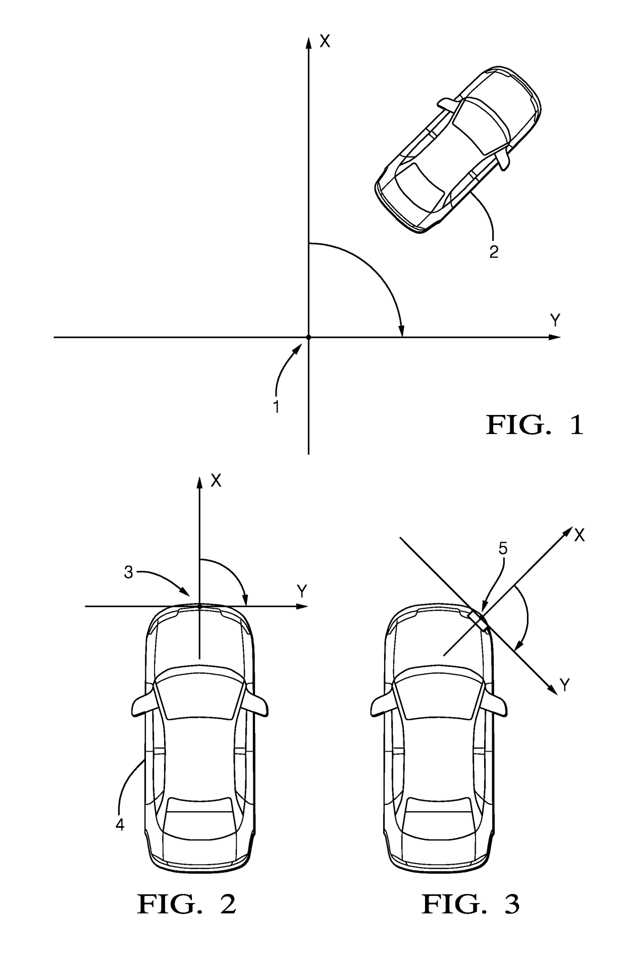
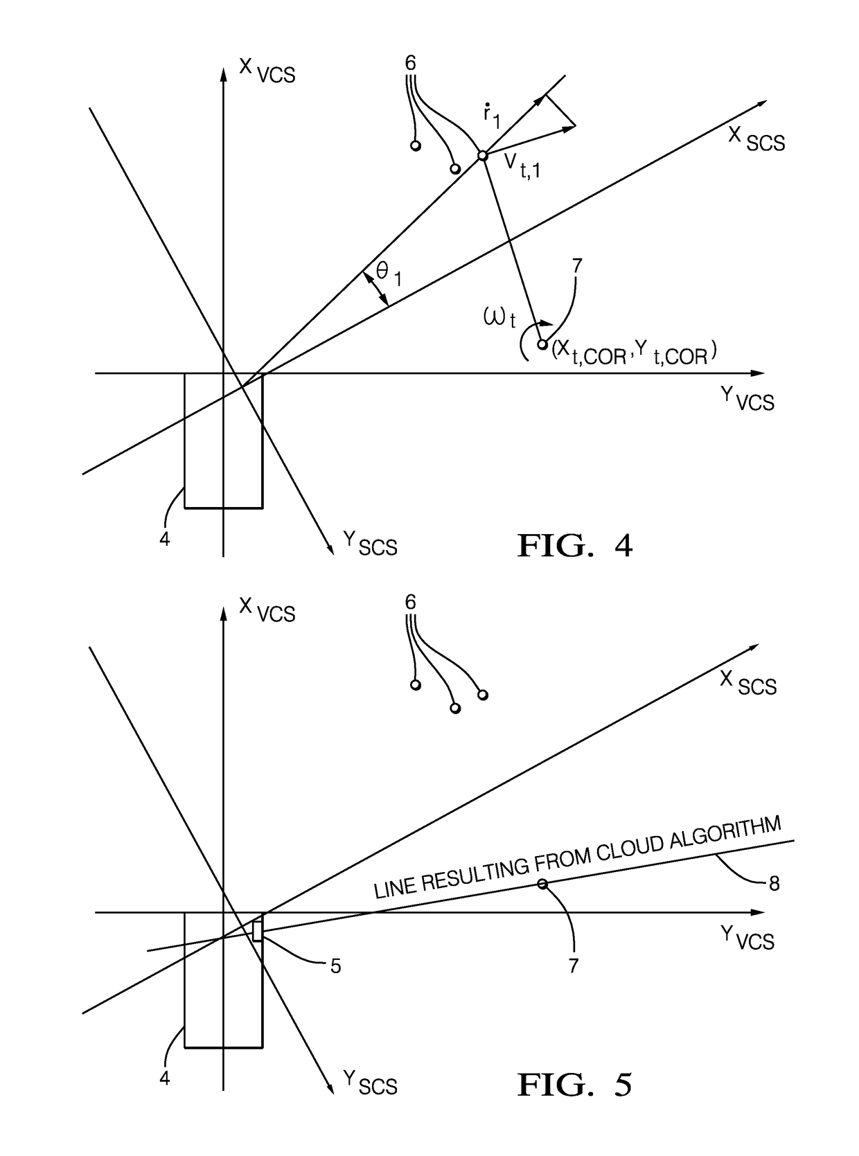
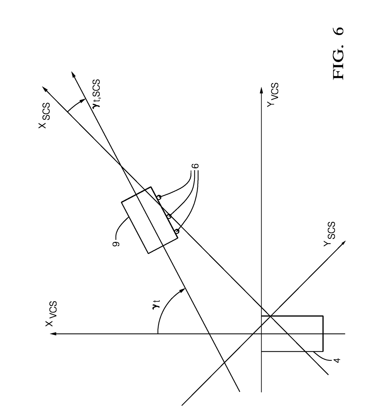
A method of determining the yaw rate ({circumflex over (ω)}t) of a target vehicle in a horizontal plane by a host vehicle equipped with a radar system, said radar system including a radar sensor unit adapted to receive signals emitted from said host vehicle by said target, comprising: emitting a radar signal at a single time-point instance and determining from a plurality (m) of point radar detections measurements captured from said target vehicle by said radar sensor unit in said single radar measurement instance, the values for each point detection of range, azimuth and range rate; [ri, θi, {dot over (r)}i]; determining the values of the longitudinal and lateral components of the range rate equation of the target (ct, st) from the results ({dot over (r)}i, θi,) and the sensor unit or host vehicle longitudinal velocity and vs is the sensor unit or host vehicle lateral velocity; determining the orientation angle of the target (γt,scs); determining the target center (xt and yt) from the results (ri, θi); determining a line lPH perpendicular to the orientation of the target and passing through the center of the target (xt,c,scs, yt,c,scs); determining a line lCA passing through the center of rotation of said target and the position of radar sensor unit of said vehicle; determining the intersection point of the lines lCA and lPH being the position of the center of rotation [{circumflex over (x)}t,COR, ŷt,COR] of the target; h) estimating and yaw rate {circumflex over (ω)}t from the position of the center of rotation found in step f) and components of range rate equation of the target (ct or st) of step b).

Description

TECHNICAL FIELD OF INVENTION[0001]This disclosure generally relates to a radar system suitable for an automated vehicle, and more particularly relates to a system that calculates a yaw-rate of the target. This invention relates to a vehicle on-board method of estimation of planar motion parameters of objects (targets such as another vehicle) detected by a (e.g. Doppler) radar. It has particular application to detected the planar motion parameters of a vehicle by a host vehicle equipped with a radar system.BACKGROUND OF INVENTION[0002]Aspects of the invention relate to an improved method of determining the instantaneous values of lateral velocity, longitudinal velocity and yaw rate of any point of a rigid body in the radar field-of-view (FOV). Aspects are applicable (but not limited) to the estimation of vehicles for automotive perception systems and can be used in Active Safety, Driver Assistance and Autonomous Driving applications.[0003]When an automated or autonomous host-vehicle ...

Claims


Application Information

Patent Timeline
IPC IPC(8): G01S13/93B60W40/114B60W30/16G01S13/931
CPCG01S13/931B60W40/114B60W30/16B60W2520/14G01S2013/9371B60K2031/0025B60W2420/408G01S7/295G01S13/582G01S13/584G01S13/42G01S13/589G01S13/726G01S2013/932G01S2013/93271
Inventor CIESLAR, DARIUSZSTACHNIK, MATEUSZKOGUT, KRZYSZTOF
Owner APTIV TECH LTD
Learn More