The break booster of the vehicle

Active Publication Date: 2018-12-13
HL MANDO CORP
View PDF5 Cites 0 Cited by
  • Summary
  • Abstract
  • Description
  • Claims
  • Application Information

AI Technical Summary

Benefits of technology

The present invention is relating to a brake booster that can be easily adjusted for a different driver's needs. The booster has a return spring structure on its outer side, making it easy to adjust the elastic force. This allows for a better match between the driver's characteristic and the operation feeling when pedaling. The booster also has a retainer that fixes the spring easily. Overall, this invention provides a more customizable and adjustable brake booster for better performance and comfort.

Problems solved by technology

However, a conventional return spring has a coupling structure which provides an elastic restoring force to return the poppet valve to an initial state, and thus generates vibrations by directly receiving an impulsive load applied to the brake booster when the brake pedal is suddenly operated.
Since vibration generation of the return spring is inversely transferred to the brake pedal through the poppet valve and an operation rod, and thus causes a driver that steps on the brake pedal to feel vibrations of the brake booster, the vibration generation of the return spring causes difficulty in adjusting an elastic force in a limited space included in the poppet valve.

Method used


Image

  • The break booster of the vehicle
  • The break booster of the vehicle
  • The break booster of the vehicle

Examples


Embodiment Construction

[0027]Hereinafter, exemplary embodiments of the present invention will be described in detail with reference to the accompanying drawings which may allow one of ordinary skill in the art to easily perform the present invention. The present invention may be implemented in various forms and is not limited to the following embodiments. Components not related to the description are omitted in the drawings to clearly describe the present invention, and the same reference symbols are used for the same or similar components in the description.

[0028]It should be further understood that the terms “include,”“including,”“have,” and / or “having” specify the presence of stated features, integers, steps, operations, elements, components, and / or groups thereof, but do not preclude the presence or addition of one or more other features, integers, steps, operations, elements, components, and / or groups thereof.

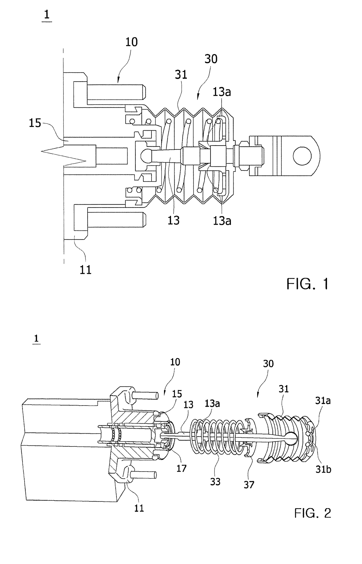
[0029]FIG. 1 is a cross-sectional view illustrating a brake booster according to an embodime...


PUM


Abstract

A brake booster is provided. The brake booster includes a poppet valve body configured to open a path for atmospheric pressure to be introduced into a variable pressure chamber by an operation rod linked with a brake pedal, and a return spring structure disposed on an outer side of the poppet valve body and configured to adjust an elastic force provided to the poppet valve body when an input of the brake pedal is released.

Description

TECHNICAL FIELD[0001]The present invention relates to a brake booster of a vehicle.BACKGROUND ART[0002]Generally, a brake apparatus (brake system) of a vehicle is an apparatus configured to generate a braking force to a running vehicle to prevent the vehicle from arbitrarily moving and is operated by a hydraulic pressure generated and supplied from a master cylinder, generally due to an operation of a brake pedal.[0003]That is, a brake pedal stepped on by a driver to generate a braking force, a brake booster provided to boost a pedal force of the brake pedal using a difference between a negative pressure (a vacuum pressure) and an atmospheric pressure generated from an engine, a master cylinder configured to convert the pedal force of the brake pedal to a hydraulic pressure, a brake main body provided to receive the hydraulic pressure from the master cylinder to generate a substantive braking force, and the like are mounted in the vehicle.[0004]That is, the brake booster is a device...

Claims


Application Information

Patent Timeline
IPC IPC(8): B60T13/57
CPCB60T13/57B60T13/143B60T13/52B60T7/04B60Y2306/09
Inventor JEON, SOO YONG
Owner HL MANDO CORP
Why Eureka
Try Eureka