
Vehicle trailer with enhanced stability

Inactive Publication Date: 2018-11-29
SHUTTLEHAWK PRODN LLC
View PDF33 Cites 1 Cited by
  • Summary
  • Abstract
  • Description
  • Claims
  • Application Information

AI Technical Summary

Benefits of technology

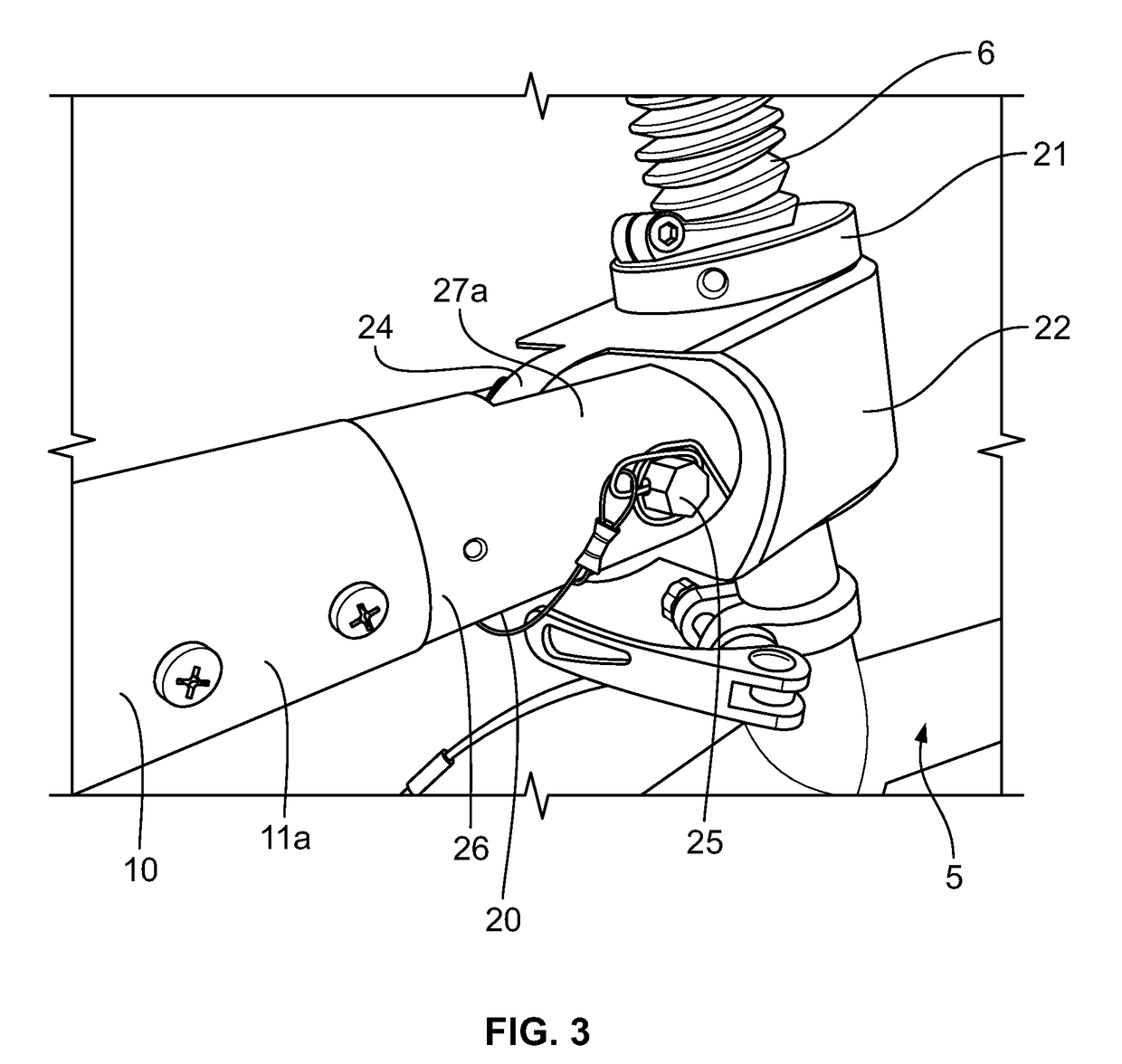
The present invention relates to a trailer that can be attached to a vehicle and carry equipment such as watersports equipment. The trailer has three axes of rotation near the end that attach to the vehicle, ensuring stability no matter the movement or orientation of the vehicle. The trailer also has versatile support bars for direct bearing of load from equipment placed on top. The trailer remains stable and the equipment does not tip over or become damaged while being pulled by the vehicle. The coupling assembly includes a first pin and a second pin for securement, and a third pin to prevent separation of the coupling assembly from the longitudinal member. The first and second portions of the coupling assembly can be overlaid with openings, allowing for the placement of additional pins.

Problems solved by technology

However, because travel is often required to get to a location where watersports can be undertaken, challenges often arise in reaching such locations, whether they are beaches or other types of shoreline.
One major obstacle is the need to use a car to pull equipment, and the heavy traffic often encountered on the road while traveling by car.
Another difficulty is carrying equipment without the use of a car.
However, existing designs do not account for the many operational conditions of a bicycle including its various positions relative to the ground during use, causing the trailer to lack stability.
Moreover, existing trailers are often unstable when loaded without being held by an operator or otherwise secured to a bicycle.
Without further improvement, existing trailers are inadequate to prevent damage to equipment loaded onto such trailers, particularly damage due to equipment tipping over.

Method used


Image

  • Vehicle trailer with enhanced stability
  • Vehicle trailer with enhanced stability
  • Vehicle trailer with enhanced stability

Examples


Embodiment Construction

[0024]The present invention relates to apparatuses, methods of assembly and methods of use of a trailer. One purpose of the trailer is to aid in transporting equipment from one location to another. The trailer can also be used to store equipment. The trailer is structured for simple securement to a vehicle such as a bicycle and for safe, efficient and non-turbulent travel over roadways, paths and trails when pulled by the vehicle.

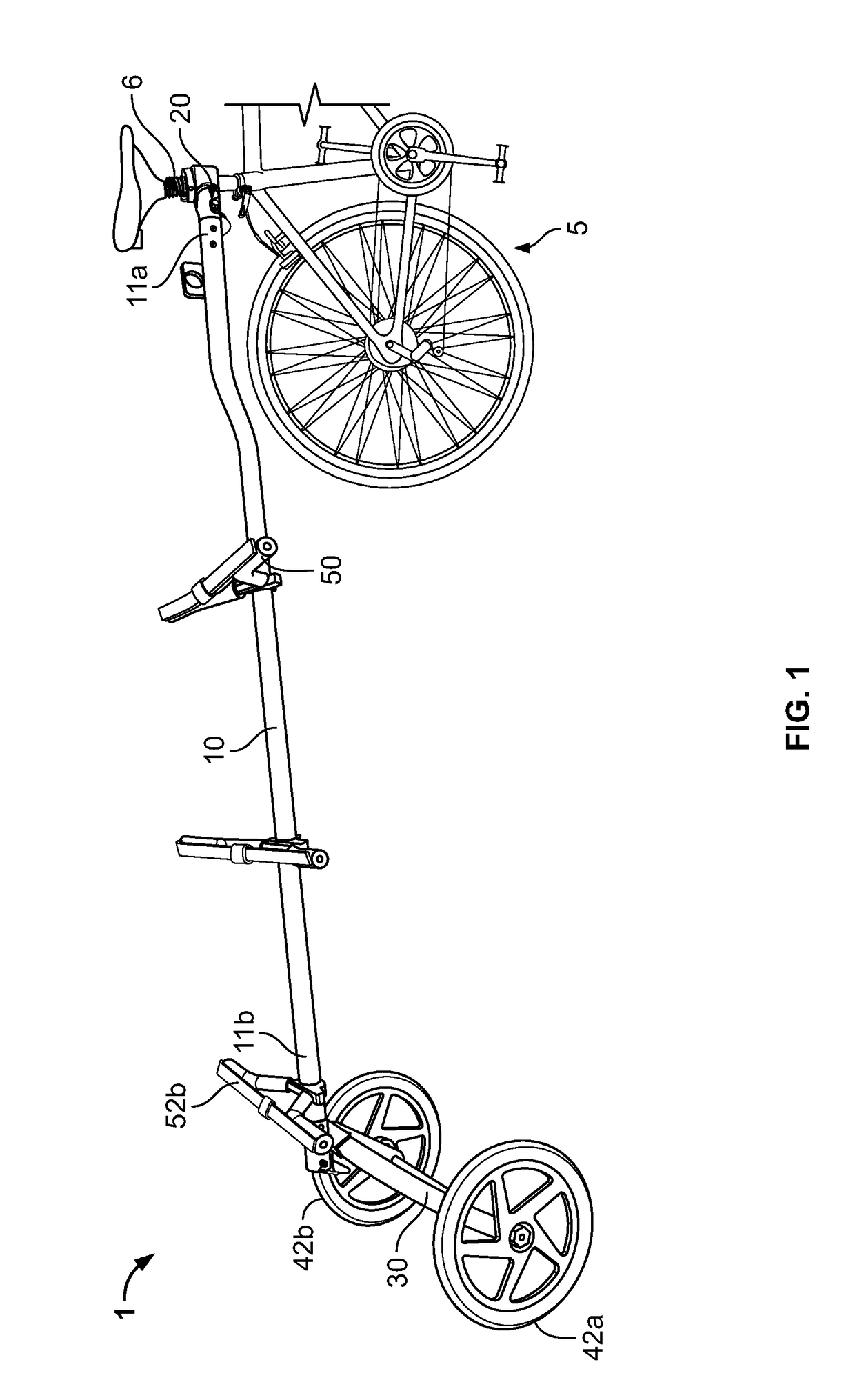
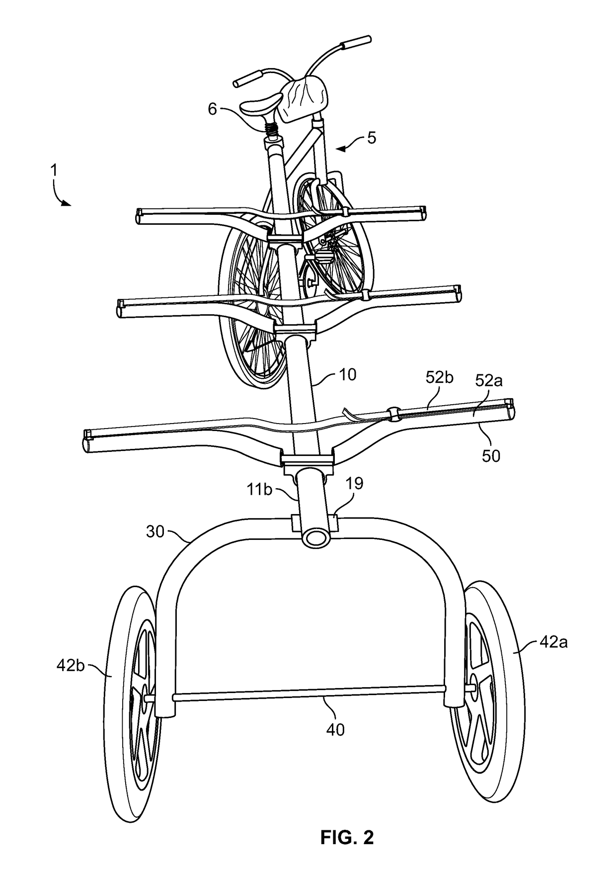
[0025]A first aspect of the present invention relates to a vehicle trailer 1, one embodiment of which is shown in FIG. 1. Trailer 1 as shown has several components including a longitudinal member 10, a coupling assembly 20, a U-shaped bar 30 and a rear axle 40 with two wheels 42a, 42b. Disposed on longitudinal member 10 are three storage support members 50. As depicted, trailer 1 is attached to a vehicle 5.

[0026]Longitudinal member 10 has a tubular shape and extends over a length spanning a majority of the trailer 1. Having a tubular shape, longitudinal mem...


PUM


Abstract

One embodiment of a trailer of the present invention includes a longitudinal member with a coupling assembly secured to the longitudinal member at one end and wheels secured to the longitudinal member at another end. The coupling assembly includes a first portion connectable to a vehicle so that when connected, the first portion is rotatable relative to the vehicle about a first axis that is approximately perpendicular to a ground surface below the vehicle. The coupling assembly further includes a second portion connected to the first portion and the longitudinal member. The second portion is rotatable relative to the first portion about a second axis. The second portion is further configured so that the longitudinal member is rotatable relative to the second portion of the coupling assembly about a third axis.

Description

BACKGROUND OF THE INVENTION[0001]Watersports are a popular activity enjoyed by many people. However, because travel is often required to get to a location where watersports can be undertaken, challenges often arise in reaching such locations, whether they are beaches or other types of shoreline. One major obstacle is the need to use a car to pull equipment, and the heavy traffic often encountered on the road while traveling by car. Another difficulty is carrying equipment without the use of a car. To address these challenges, trailers have been developed for use with bicycles, which may be operated without being held up by traffic.[0002]To improve maneuverability of bicycle trailers carrying equipment, existing designs have included simple structural features that allow some movement of the trailer relative to a bicycle pulling it. However, existing designs do not account for the many operational conditions of a bicycle including its various positions relative to the ground during u...

Claims


Application Information

Patent Timeline
IPC IPC(8): B60P7/08B62D7/22
CPCB60P7/0815B62D12/02B62D7/22B62K27/003B62K27/12
Inventor SHUTTLEWORTH, EDHAWK, DOUGLAS
Owner SHUTTLEHAWK PRODN LLC
Learn More