Eureka AIR delivers breakthrough ideas for toughest innovation challenges, trusted by R&D personnel around the world.

Assist device

a technology of a support device and a splint, which is applied in the field of support devices, can solve the problems of difficult to detect the pivot angle with a high resolution, difficult to assist the user in performing the lifting of objects, and the user cannot stand firm, so as to achieve the effect of efficiently continuing the motion

Inactive Publication Date: 2018-11-29
JTEKT CORP
View PDF0 Cites 9 Cited by
  • Summary
  • Abstract
  • Description
  • Claims
  • Application Information

AI Technical Summary

Benefits of technology

This patent describes an assist device that can detect the angle at which a person's leg is pivoting and provide more precise support. This allows the person to move more efficiently and with less effort. The device also adjusts its support based on the person's motion, so they can continue the motion with greater ease. Overall, this technology is designed to make it easier for people to perform various tasks with greater accuracy and ease.

Problems solved by technology

Accordingly, when the range of the pivot angle is relatively small and the pivot angle of the thigh is detected with the use of an ordinary angle detection device, it may be difficult to detect the pivot angle with a high resolution.
Therefore, for example, when the user lifts up an object, the user cannot perform a motion of spreading the legs in the right-left direction and standing firm.
Thus, it may be difficult to assist the user in performing an object lift-up motion or the like appropriately.

Method used


Image

  • Assist device
  • Assist device
  • Assist device

Examples


first embodiment

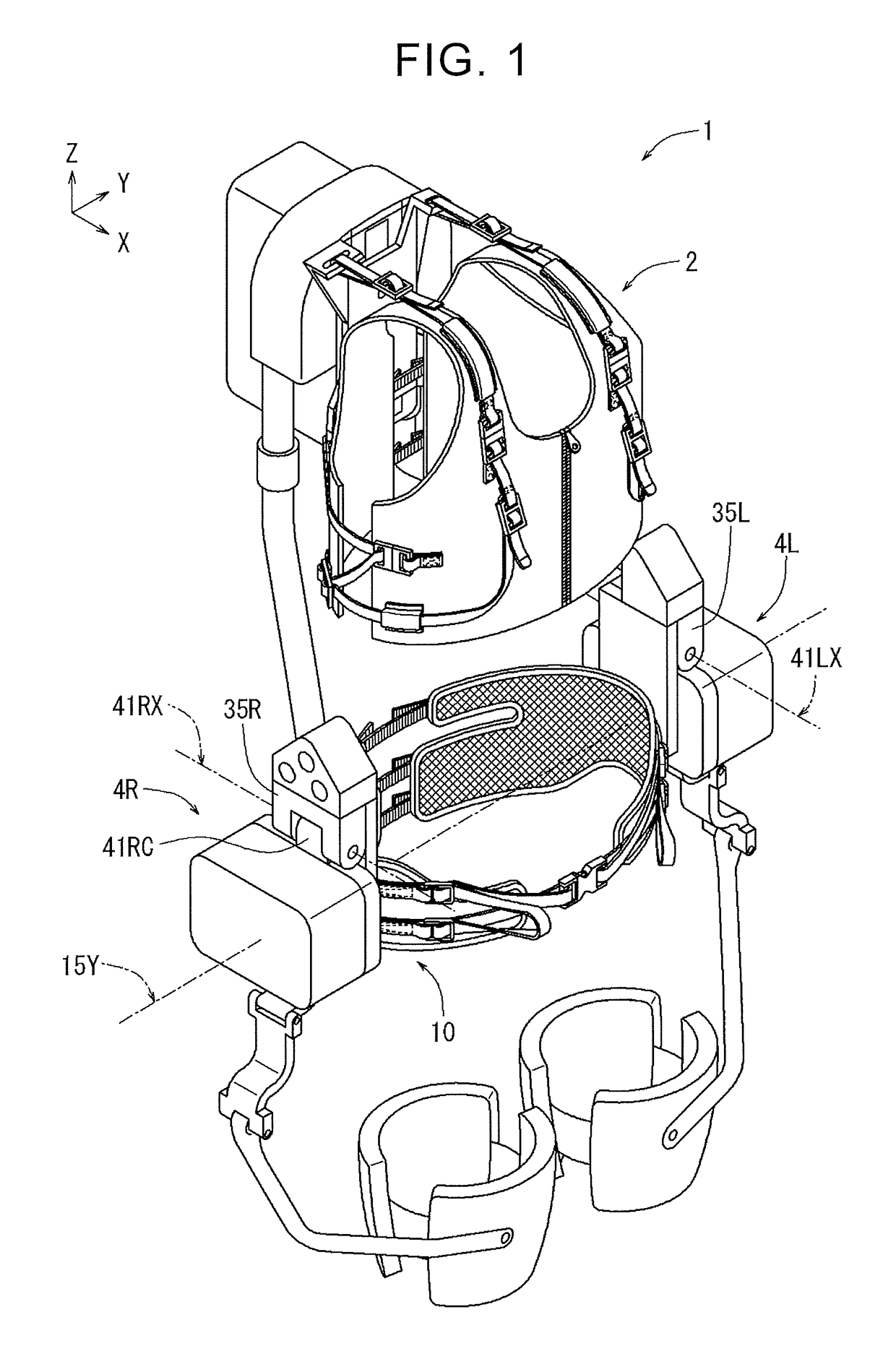
[0082]Hereinbelow, the overall structure of an assist device 1 will be described with reference to FIGS. 1 to 21. The assist device 1 is, for example, a device that assists pivoting of the thighs relative to the waist when a user lifts up an object (for example, a parcel or baggage) or when the user walks. In the drawings, X-, Y-, and Z-axes are perpendicular to each other, and when viewed from the user wearing the assist device, the X-axis direction corresponds to a forward direction, the Y-axis direction to a leftward direction, and the Z-axis direction to an upward direction.

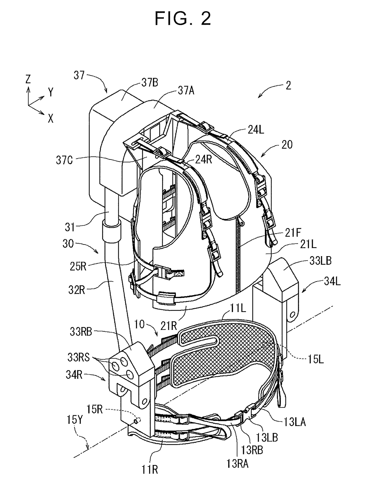
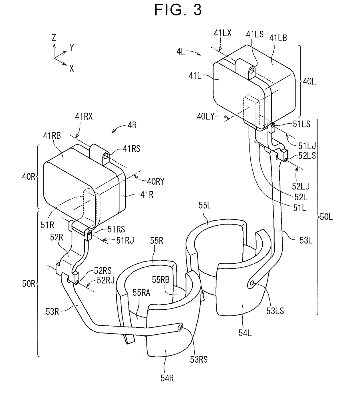
[0083]FIG. 1 illustrates the overall external appearance of the assist device 1 of the first embodiment. The assist device 1 includes a body wearing unit 2 (see FIG. 2), a right actuator unit 4R (see FIG. 3), and a left actuator unit 4L (see FIG. 3). The body wearing unit 2 is configured to be worn on the body including regions around assist target body parts (the thighs in an example of the present embodime...

second embodiment

[0200]Further, as illustrated in FIGS. 35, 39, a connecting portion 241RS of the right actuator unit 204R is fixed to the lower end of a right sub-frame 232R. Accordingly, in the second embodiment, the right actuator unit 204R does not pivot in the right-left direction relative to the right sub-frame 232R, and the right actuator unit 204R does not pivot in the up-down direction relative to the right sub-frame 232R. This makes it possible to prevent a decrease in transmission efficiency due to unnecessary pivoting of the actuator unit in work (movement) in a state where the assist torque is large or a rapid change of the assist torque is required. Further, pivoting of the upper part of the right actuator unit 204R in the up-down direction is also prohibited in the state where the assist torque is large or a change of the assist torque is fast. This makes it possible to further prevent a decrease in transmission efficiency. That is, when the assist torque is large or a change of the a...


PUM


Abstract

An assist device includes a body wearing unit, and an actuator unit. The actuator unit includes an output link and an actuator having an output shaft. The output shaft is connected to the output link via a speed reducer configured to reduce a pivot angle from the output shaft. The speed reducer includes an accelerating shaft connected to the output shaft and a decelerating shaft connected to the output link. The accelerating shaft of the speed reducer is provided with an output link pivot angle detection unit configured to detect a pivot angle of the output link.

Description

INCORPORATION BY REFERENCE[0001]The disclosure of Japanese Patent Application No. 2017-105015 filed on May 26, 2017 and Japanese Patent Application No. 2017-217564 filed on Nov. 10, 2017, each including the specification, drawings and abstract, is incorporated herein by reference in its entirety.BACKGROUND1. Technical Field[0002]The disclosure relates to an assist device that assists the motion of an assist target body part of a user.2. Description of Related Art[0003]For example, Japanese Unexamined Patent Application Publication No. 2016-150420 (JP 2016-150420 A) describes a power assist robotic device including a waist frame (a main frame) and a thigh frame and configured to assist the motion of the thigh of a wearer by causing the thigh frame worn on the thigh of the wearer to pivot relative to the waist frame. An electric motor is fixed to a first end (the upper end) of the thigh frame, and a second end (the lower end) of the thigh frame is worn on the thigh of the wearer. A ro...

Claims


Application Information

Patent Timeline
Patent Type & Authority Applications(United States)
IPC IPC(8): A61H1/02
CPCA61H1/0262A61H2201/1652A61H2201/1463A61H2201/5069A61H2201/1207A61H2201/5007B25J9/0006A61H1/0237A61H1/0244A61H3/008A61H2201/0107A61H2201/0192A61H2201/1616A61H2201/1621A61H2201/163A61H2201/1642A61H2201/1676A61H2201/169A61H2203/0406A61H2201/1626
Inventor OHTA, HIROMICHIOHTSUBO, KAZUYOSHIKATOH, YOSHINOBUSATO, HISATAKA
Owner JTEKT CORP
Why Eureka
Eureka Blog
Learn More