Eureka AIR delivers breakthrough ideas for toughest innovation challenges, trusted by R&D personnel around the world.

Systems and Methods for Automated Camera Calibration

a technology of automatic camera calibration and system, applied in the field of system and method for automatic camera calibration, can solve the problems of difficult detection and localization of image features that correspond to arbitrary objects across multiple images, affect the ability to recognize features, and current imaging devices are susceptible to noise, blur, distortion, etc., and achieve the effect of maximizing similarities

Active Publication Date: 2018-11-22
SPORTLOGIQ
View PDF0 Cites 39 Cited by
  • Summary
  • Abstract
  • Description
  • Claims
  • Application Information

AI Technical Summary

Benefits of technology

The patent text describes a method for adjusting parameters to reduce the difference between a template and a sequence of images, or to increase the similarity between the camera and the template in terms of their coordinate systems.

Problems solved by technology

Detecting and localizing image features (points, lines, conics) that correspond to an arbitrary object across multiple images can be a challenging problem.
Current imaging devices are susceptible to noise, blur, distortion, and illumination variations, which impacts the ability of recognizing a feature in the image.
Employing such calibration patterns for outdoor cameras which are typically far from the ground plane could be impractical, because the size of the pattern might be in the order of couple of meters to be reliably detected.
A particular example of such a situation in which the use of a calibration pattern is not practical is a broadcast camera showing a sporting event.
The drawback associated with these image-landmark based calibration methods is that they rely on finding good correspondences between images and the real-world geometry.
Unless the real-world object with known geometry has easily identifiable landmarks, point correspondences usually leads to unreliable results.
Another problem arises when the camera parameters are changing over time (e.g. the lens focal length and camera orientation in broadcast camera covering a sport event) it is required to re-calibrate the camera and estimate the new sets of camera parameters.
The calibration typically cannot be done using conventional techniques and it is required to estimate camera parameters at every frame based on the new observations.
Although these techniques are widely used in computer vision systems, it has been found to not be easy to (re-)estimate camera parameters if they are constantly changing over time.
One of the problems associated with these family of algorithms is the fact that the error is accumulated over time and hence and eventually the estimated parameters start to diverge from the actual ones and there is not any way to overcome that issue, unless the calibration is being performed again.
In addition, in outdoor scenes and broadcast sport videos the use of calibration patterns can be considered impractical and landmark feature points are often rare and lines and curves are usually dominant visible features [2].
Accurately finding lines in images has inherent difficulties compared to finding point landmarks, because it is involved in combining information across multiple pixels.
In addition, lens distortion can make lines appear as curves and hence, detecting lines in distorted images becomes more complicated [9].
Accordingly, curved lines usually are more problematic and sometimes it might not be possible to find parametric fits for a curvilinear shape.
Therefore, the accuracy of robustness of such methods are susceptible to the noisy extracted image features [4].
In summary, almost all calibration methods highly rely on the quality of the feature-point or line detections obtained from local corner or edge features and hence, the detection algorithms are affecting robustness, accuracy, and practicality of the calibration systems.

Method used


Image

  • Systems and Methods for Automated Camera Calibration
  • Systems and Methods for Automated Camera Calibration
  • Systems and Methods for Automated Camera Calibration

Examples


Embodiment Construction

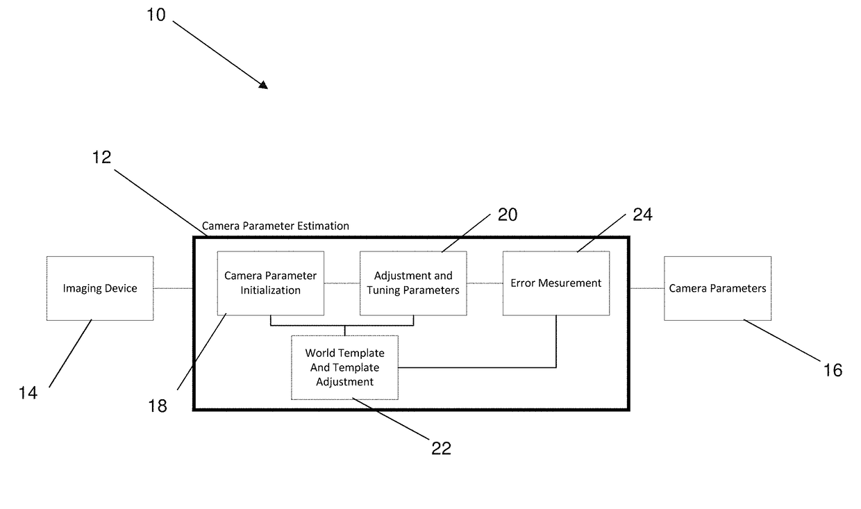
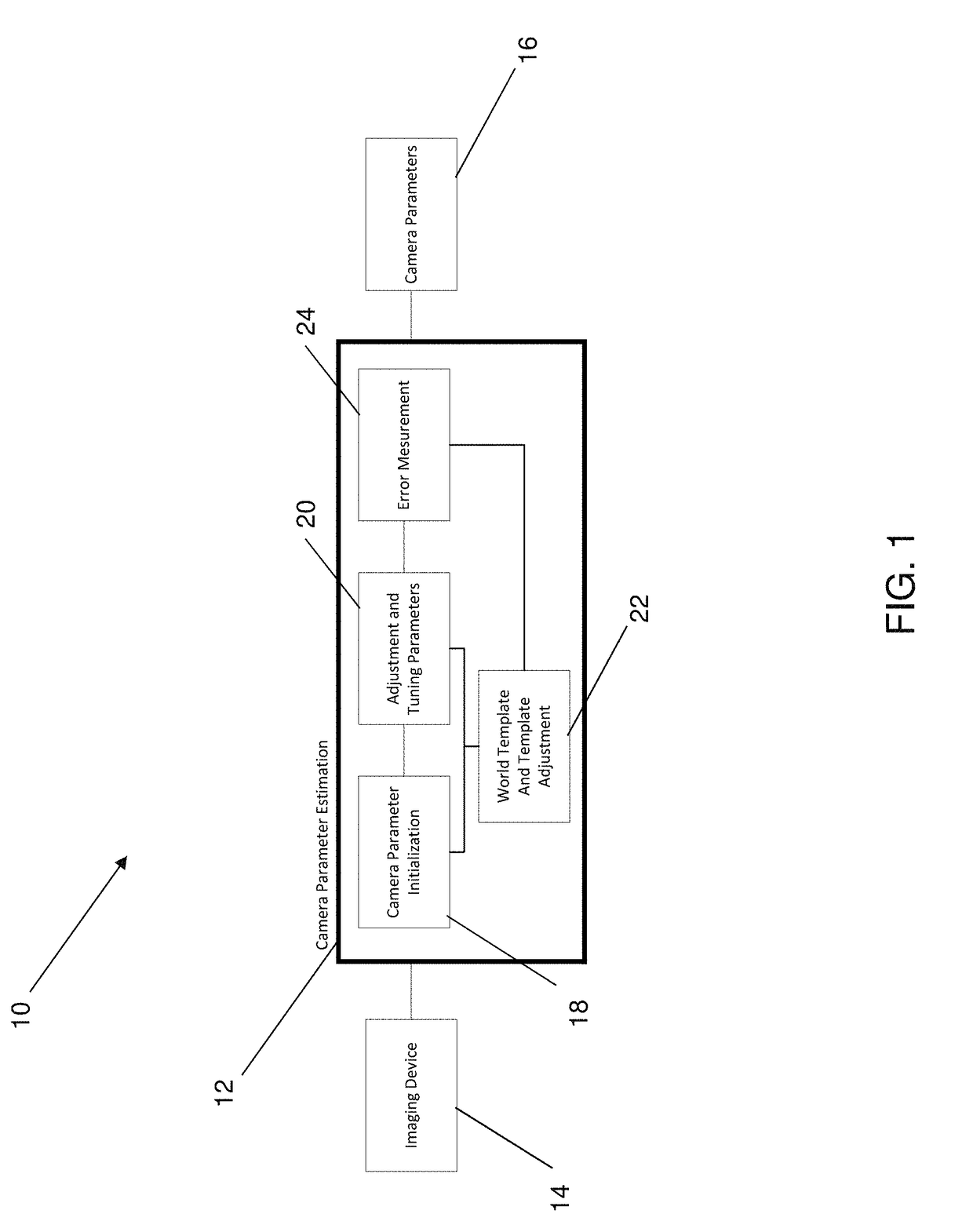
[0031]The following relates to methods and systems for iteratively estimating the ground plane, camera parameters and planar homography transformation in a sequence of images. The method includes receiving an image from an imaging device or a camera of 3D objects or 2D planes with known dimensions, referred to herein as “templates”.

[0032]Two iterative camera parameter adjustment techniques are presented for optimizing the alignment between the image and the object template. The camera parameters and planar homography transform estimation are being updated using an iterative process at every image frame, by either considering point correspondence or by maximizing mutual information between the template target and the image frame.

[0033]It can be appreciated that although the principles set forth herein are described in the context of videos (or images) of sport fields using a regular camera device, the techniques can be applied to any other applications such as simultaneous localizati...


PUM


Abstract

A system and method are provided for calibrating and re-calibrating an imaging device. The image device comprises at least one varying intrinsic or extrinsic parameter value based on a view of 3D shapes and a 2D template therefor. The method and system are operable to receive a sequence of images from the imaging device, wherein a planar surface with known geometry is observable from the sequence of images; perform an initial estimation of a set of camera parameters for a given image frame; perform a parameter adjustment operation to minimize a dissimilarity between the template and the sequence of images; perform a parameter adjustment operation to maximize similarities in either the camera's coordinate system or the template's coordinate system; and update an adaptive world template to incorporate an additional stable point from the observed images to the template.

Description

CROSS-REFERENCE TO RELATED APPLICATION(S)[0001]This application is a continuation of PCT Application No. PCT / CA2017 / 050117 filed on Feb. 2, 2017 which claims priority to U.S. Provisional Patent Application No. 62 / 290,558 filed on Feb. 3, 2016, both incorporated herein by reference.TECHNICAL FIELD[0002]The following relates to systems and methods for automated camera calibration.DESCRIPTION OF THE RELATED ART[0003]Camera calibration is used for estimating the parameters of a geometric camera model, which establishes a relationship between three-dimensional points in a scene with two-dimensional points in an image. Estimating these parameters is often considered a fundamental task in computer vision research. Any vision application which relies on computing metric information from images requires the intrinsic (properties of the lens and capture device) and extrinsic (position and orientation) camera parameters to be known.[0004]Decades of research on this topic have produced a divers...

Claims


Application Information

Patent Timeline
Patent Type & Authority Applications(United States)
IPC IPC(8): G06T7/80G06T7/13G06T7/62G06T7/33
CPCG06T7/80G06T7/13G06T7/62G06T7/337G06T2207/20076G03B43/00G03B35/00H04N17/002G06T2207/20084G06T2207/30204G06T2207/30228
Inventor JAVAN ROSHTKHARI, MEHRSANGAMBOA HIGUERA, JUAN CAMILODUDEK, GREGORY LEWIS
Owner SPORTLOGIQ
Why Eureka
Eureka Blog
Learn More