
Optical filter

a filter and optical technology, applied in the field of optical filters, can solve the problems of large errors in the retrieved temperature and water vapor profiles, limited spatial and temporal resolution, and inability to observe key atmospheric features, and achieve the effect of substantial background noise suppression and constant transmission

Active Publication Date: 2018-11-08
NASA
View PDF0 Cites 3 Cited by
  • Summary
  • Abstract
  • Description
  • Claims
  • Application Information

AI Technical Summary

Benefits of technology

The patent describes a filter for a micropulse differential absorption LIDAR that can filter out background noise and ensure that the laser wavelengths are transmitted correctly. This results in a more accurate detection of target substances using the LIDAR technology. The technical effect of this invention is to improve the quality of the detected signals and enhance the accuracy of the analysis of target substances.

Problems solved by technology

But the limited spatial and temporal resolution of the current state of technology prohibits observations of key atmospheric features required for accurate forecasting of mesoscale high-impact weather events like thunderstorms.
During cloudy conditions, retrieval of temperature and water vapor profiles are sensitive to the cloud properties leading to larger errors in the retrieved temperature and water vapor profiles.
Some of these interactions, such as Mie and Rayleigh scattering, result in backscattered photons.
Prior shared telescope designs have illuminated the entire primary minor to expand the beam with the telescope, however, losing light blocked by the secondary minor.
Beam shaping alone cannot solve the performance problems experienced by prior micropulse LIDAR systems if the beam is expanded to the full diameter of the telescope, however, because prior designs have needed polarization transmit / receive switches to separate transmit and receive paths in the shared telescope.
Switching with the MEMS switch created several performance limitations.
Second, wavelength switching on timescales of several seconds can result in errors due to rapid changes between the online and offline backscattered signals resulting from fluctuations in the aerosol distributions on short time scales.

Method used


Image

  • Optical filter
  • Optical filter
  • Optical filter

Examples


Embodiment Construction

[0022]FIGS. 1-5 and the following description depict specific examples to teach those skilled in the art how to make and use the best mode of the Application. For the purpose of teaching inventive principles, some conventional aspects have been simplified or omitted. Those skilled in the art will appreciate variations from these examples that fall within the scope of the Application. Those skilled in the art will appreciate that the features described below can be combined in various ways to form multiple variations of the Application. As a result, the Application is not limited to the specific examples described below, but only by the claims and their equivalents.

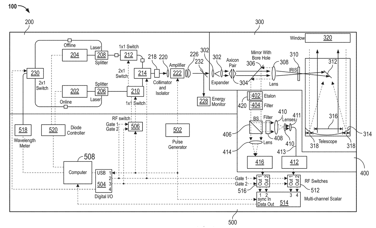
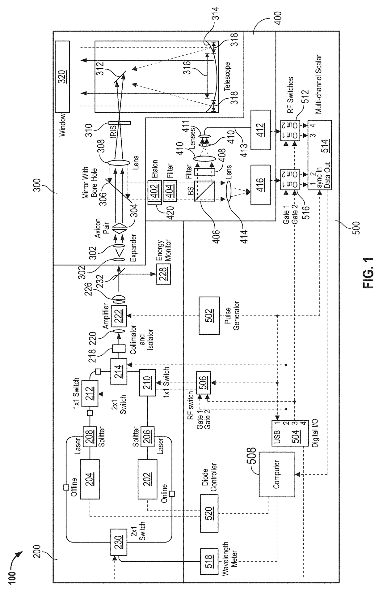
[0023]FIG. 1 depicts micropulse differential absorption LIDAR 100. Micropulse differential absorption LIDAR 100 includes a beam transmitter 200, a shared optics and telescope 300, an optical receiver 400, and an electronics 500. Micropulse differential absorption LIDAR 100 is a LIDAR that can operate with two separate lase...


PUM

PropertyMeasurementUnit
altitudeaaaaaaaaaa
FWHMaaaaaaaaaa
switching timeaaaaaaaaaa

Abstract

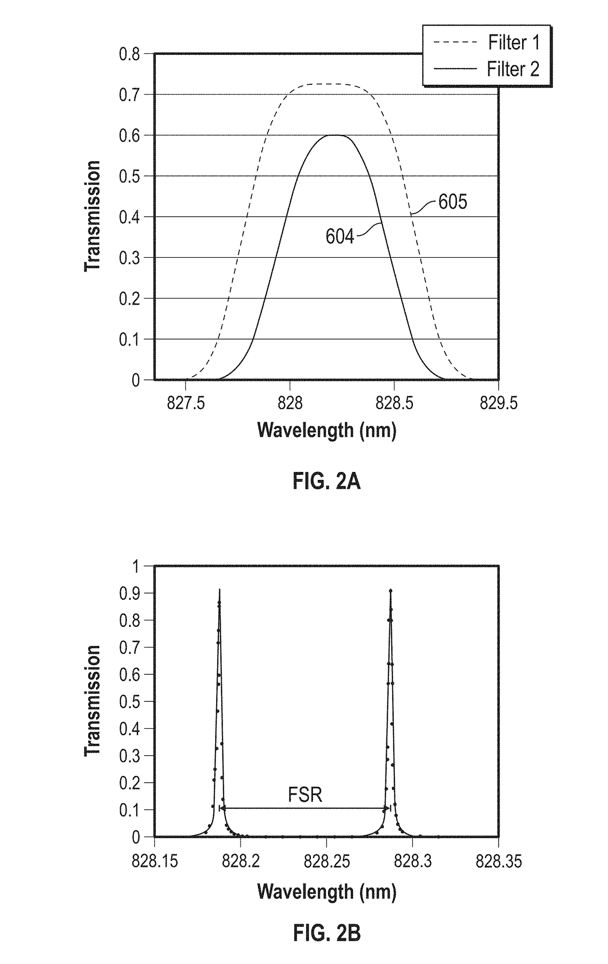
A filter for a micropulse differential absorption LIDAR is provided. The filter comprises an etalon including a free spectral range substantially the same as a difference between a first laser wavelength and a second laser wavelength, the etalon further including a finesse providing substantial background noise suppression and substantially constant transmission of the first laser wavelength and the second laser wavelength over a predetermined range of wavelengths, and a first filter having a first filter bandpass selected to include the first laser wavelength and the second laser wavelength.

Description

CROSS REFERENCE TO RELATED APPLICATIONS[0001]This patent application is a divisional of U.S. patent application Ser. No. 15 / 139,925 filed on Apr. 27, 2016, which claims the benefit of priority to U.S. Provisional Patent Application No. 62 / 167,118, filed on May 27, 2015, and the contents of both applications are hereby incorporated by reference in their entirety.STATEMENT REGARDING FEDERALLY SPONSORED RESEARCH OR DEVELOPMENT[0002]The invention described herein was made in part by an employee of the United States Government and may be manufactured and used by or for the Government of the United States of America for governmental purposes without the payment of any royalties thereon or therefore. The U.S. Government also has the right in limited circumstances to require the patent owner to license others on reasonable terms as provided for by the terms of Agreement No. AGS-0753581, awarded by a National Science Foundation and National Center for Atmospheric Research cooperative agreeme...

Claims


Application Information

Patent Timeline
Patent Type & Authority Applications(United States)
IPC IPC(8): G01S7/481G01S17/95G01S17/10G01S7/484G01N21/53G01N21/17G01N21/47G01S17/18
CPCG01N2021/4709G01N2021/1795G01N21/538G01S7/4816G01S7/4814G01S17/95G01S17/107G01S7/484G01S7/4812G01S17/18Y02A90/10
Inventor SPULER, SCOTT M.REPASKY, KEVIN S.NEHRIR, AMIN R.
Owner NASA
Learn More