Vehicular power transmitting system

Active Publication Date: 2018-10-25
TOYOTA JIDOSHA KK +1
View PDF0 Cites 1 Cited by
  • Summary
  • Abstract
  • Description
  • Claims
  • Application Information

AI Technical Summary

Benefits of technology

The present invention provides a vehicular power transmitting system that reduces gear noise and improves the NV-free performance of the system. The invention achieves this by reducing the vibrations transmitted through the shifting shaft support portion and the outer housing wall of the casing, which are caused by the gear-meshing vibrations of the planetary gear set. The invention achieves this by placing the fixing portion of the reverse drive brake in a position that is outside the predetermined circumferential portion of the brake retaining portion, which is close to the shifting shaft support portion. This reduces the vibrations transmitted through the shifting shaft support portion and the outer housing wall, resulting in less noise and improved performance of the power transmitting system.

Problems solved by technology

Accordingly, vibrations generated upon gear meshing engagement of the planetary gear set (“gear-meshing vibrations”) are transmitted to a brake retaining portion of the casing at which the reverse drive brake is retained, and are further transmitted to an outer housing wall of the casing, whereby the vibrations give rise to a risk of generation of a noise (“gear noise”).
Where a shifting shaft of the gear type transmission mechanism is disposed on the above-indicated second axis positioned between the outer housing wall of the casing and the above-indicated first axis, and is supported at a shifting shaft support portion positioned between the outer housing wall and the brake retaining portion, the gear-meshing vibrations transmitted to the brake retaining portion are relatively easily transmitted to the outer housing wall through the shifting shaft support portion, which has a comparatively high degree of rigidity, so that there is a considerably high risk of generation of the above-indicated gear noise, whereby the vehicular power transmitting system in question suffers from a low degree of NV-free performance (noise / vibration-free performance).

Method used


Image

  • Vehicular power transmitting system
  • Vehicular power transmitting system
  • Vehicular power transmitting system

Examples


embodiment

[0022]A preferred embodiment of this invention will be described in detail by reference to the drawings. It is noted that the drawings are simplified or transformed as needed, and do not necessarily accurately represent the dimensions and shapes of various elements of the embodiment.

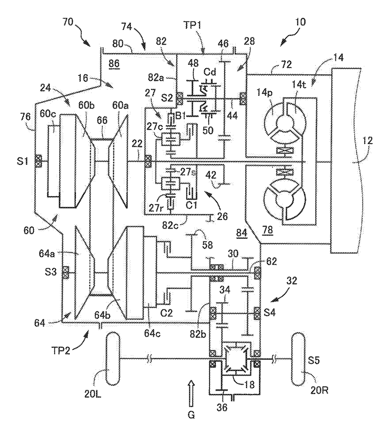
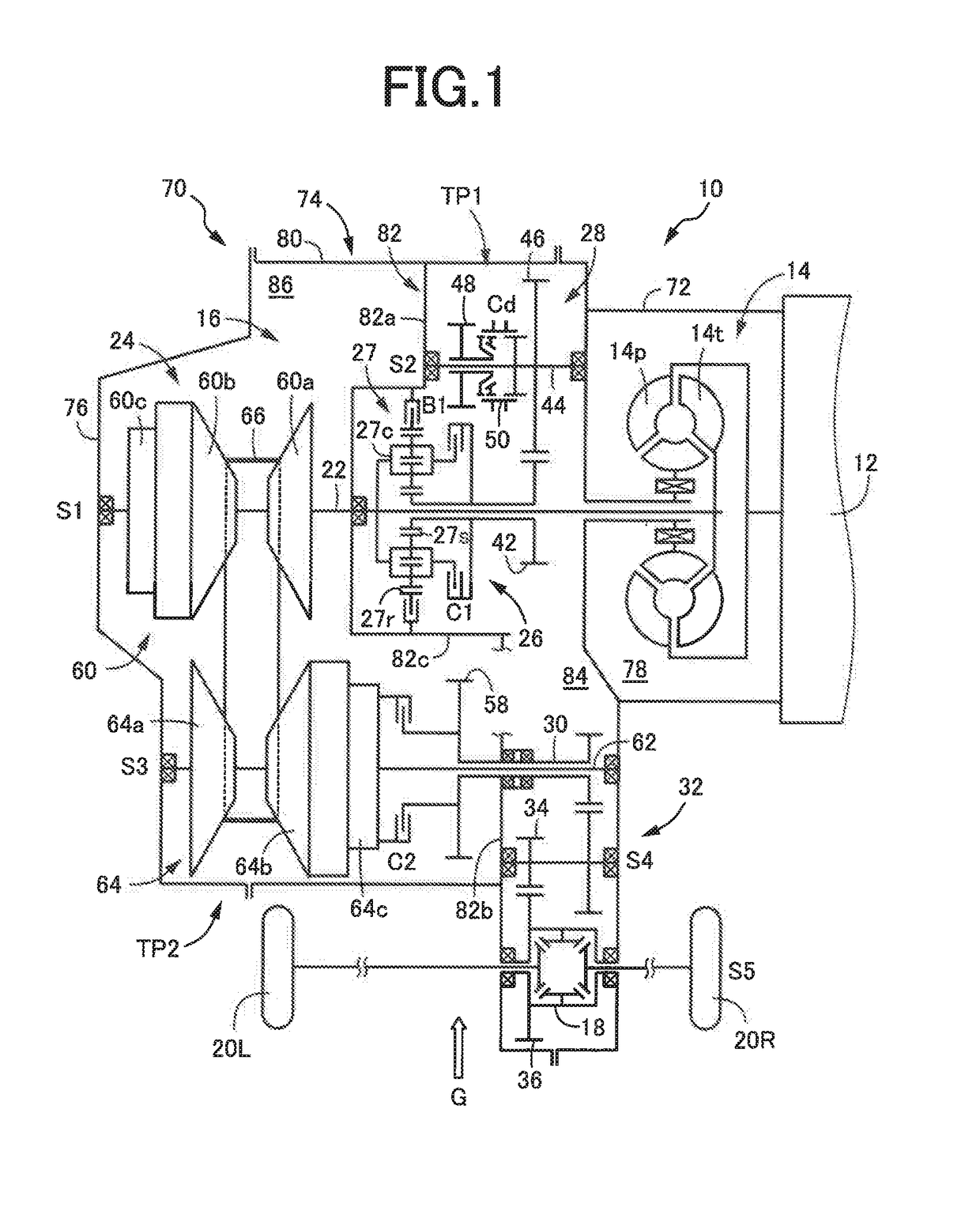
[0023]Reference is first made to FIG. 1, which is the schematic view showing a vehicular power transmitting system 10 according to one embodiment of this invention, such that a plurality of mutually parallel axes of the vehicular power transmitting system 10 lie in one plane. This vehicular power transmitting system 10 is a transaxle of a transverse type the plurality of axes of which are parallel to a width or transverse direction of a vehicle provided with the vehicular power transmitting system 10. In the present embodiment, the vehicular power transmitting system 10 is provided on an FF (front-engine front-drive) vehicle. The vehicle is provided with a vehicle driving power source in the form of an i...


PUM


Abstract

In a vehicular power transmitting system, a fixing portion of a brake retaining portion receives a reaction force from a reverse drive brake and is located in a portion of a circumference of the brake retaining portion, which is outside a predetermined circumferential portion close to the shifting shaft support portion and is defined by a pair of lines tangent to a circumference of the shifting shaft and parallel to a straight line connecting first and second axes and located on opposite sides of the straight line, as seen in a plane normal to the first axis, where a forward / reverse switching device including the reverse drive brake is disposed on the first axis, and a gear type transmission is disposed on the first axis and the second axis and an outer housing wall and a partition wall radially inwardly extending from the outer housing wall are provided.

Description

[0001]This application claims priority from Japanese Patent Application No. 2017-086646 filed on Apr. 25, 2017, the disclosure of which is herein incorporated by reference in its entirety.FIELD OF THE INVENTION[0002]The present invention relates generally to a vehicular power transmitting system, and more particularly to an improvement of a vehicular power transmitting system of a type which includes a planetary gear set having a selectively fixed rotary element and which is configured to be placed in a reverse drive position when the selectively fixed rotary element is fixed to a casing with a reverse drive brake.BACKGROUND OF THE INVENTION[0003]There is known a vehicular power transmitting system which includes a forward / reverse switching device of a planetary gear type disposed on a first axis, and a gear type transmission mechanism disposed on the first axis and a second axis parallel to the first axis, and which has a first power transmitting path through which a drive force of...

Claims


Application Information

Patent Timeline
IPC IPC(8): F16H1/28F16H57/10F16H57/00
CPCF16H1/2845F16H57/10F16H57/0037F16H63/3026F16H37/0813F16H37/022F16H57/028F16H57/08F16H2037/026F16H57/035F16H2057/0216
Inventor TAKEDA, YASUNORITERAMOTO, TAKAYUKIITAZU, NAOKINARUSE, KENTAROOISHI, YOSHIHIROFUJITA, HIROSHI
Owner TOYOTA JIDOSHA KK
Why Eureka
Try Eureka