Self-driving building energy engine

a self-driving, building energy technology, applied in the direction of electric variable regulation, process and machine control, instruments, etc., can solve the problems of not producing accurate, difficult to verify, and not producing accura

Active Publication Date: 2018-10-18
MELROK
View PDF13 Cites 8 Cited by
  • Summary
  • Abstract
  • Description
  • Claims
  • Application Information

AI Technical Summary

Benefits of technology

[0015]For purposes of summarizing the disclosure, certain aspects, advantages and novel features of the inventions have been described herein. It is to be understood that not necessarily all such advantages may be achieved in accordance with any particular embodiment of the invention. Thus, the invention may be embodied or carried out in a manner that achieves or optimizes one advantage or group of advantages as taught herein without necessarily achieving other advantages as may be taught or suggested herein.

Problems solved by technology

These rely on static analytics and do not produce accurate results.
The Energy Star® ratings rely on static analytics, estimates, and forecasting, and do not produce accurate results and can be difficult to verify.
As a result of the lack of accurate and consistently reliable measurement and verification standards, false claims of carbon credits, Negawatts (energy saved as a result of energy conservation or increased efficiency), and other energy reductions are being made.
Further, the lack of accurate and consistent energy assessment makes it difficult to accurately determine the benefit of corrective actions to equipment and systems, to normalize energy conservation investments, to calculate paybacks from energy conservation investments and retrofits of buildings, and the like.

Method used


Image

  • Self-driving building energy engine
  • Self-driving building energy engine
  • Self-driving building energy engine

Examples


Embodiment Construction

[0027]The features of the systems and methods will now be described with reference to the drawings summarized above. Throughout the drawings, reference numbers are re-used to indicate correspondence between referenced elements. The drawings, associated descriptions, and specific implementation are provided to illustrate embodiments of the inventions and not to limit the scope of the disclosure.

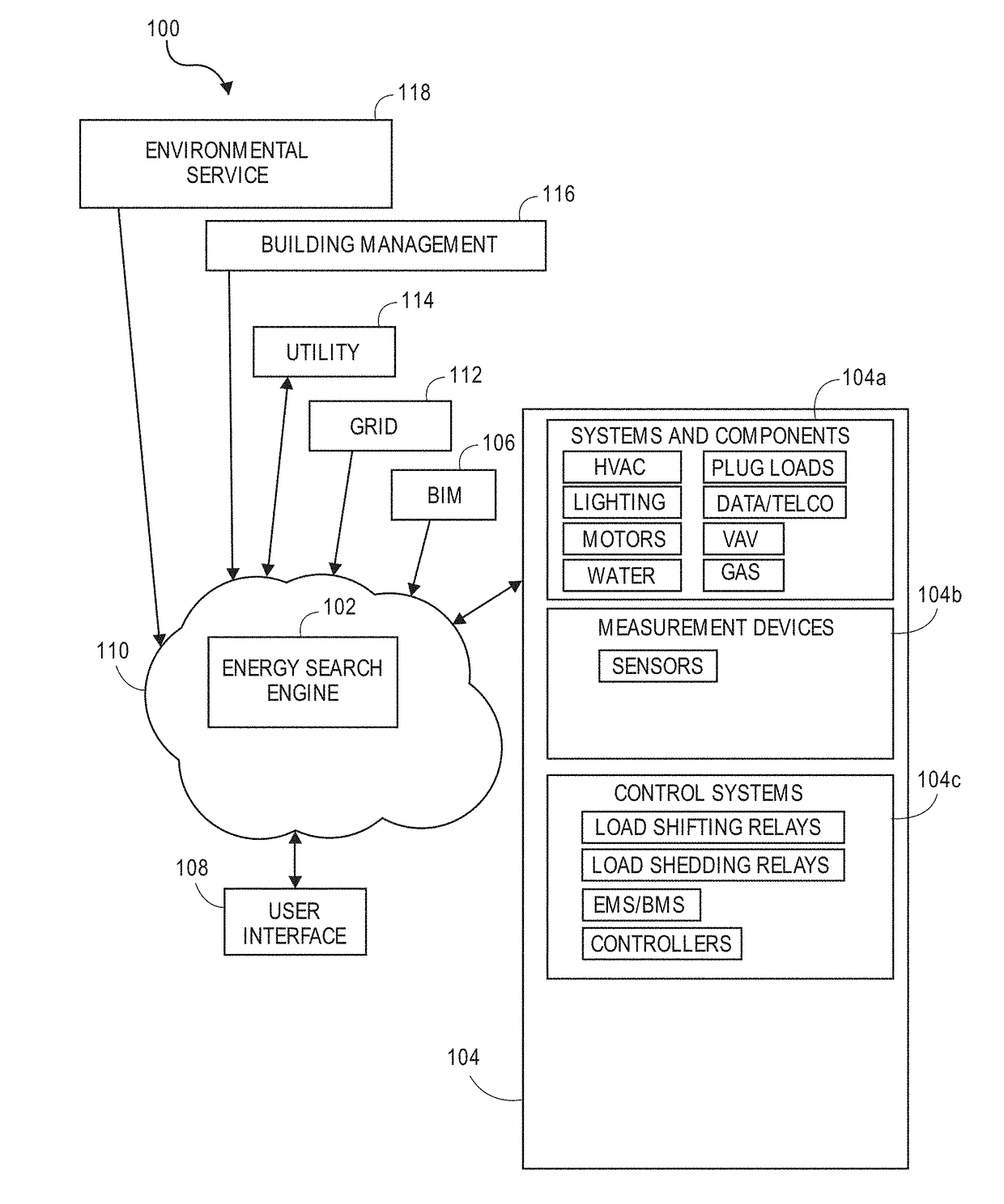
[0028]Embodiments of an energy search engine use dynamic energy related data to determine how well a facility is using energy and to identify wasted energy. Further embodiments dynamically guide building system adjustments to reduce energy waste, and verify the results of such actions. For example, contemporary heating, ventilation, and air conditioning (HVAC) systems use a combination of chilled coolant or chilled water, evaporative coils, forced air ducting, and hot water intermixed to provide comfort and fresh air to occupants of buildings. To provide this comfort, many building HVAC system...


PUM


Abstract

Systems and methods dynamically assess energy efficiency by obtaining a minimum energy consumption of a system, receiving in a substantially continuous way a measurement of actual energy consumption of the system, and comparing the minimum energy consumption to the measurement of actual energy consumption to calculate a substantially continuous energy performance assessment. The system further provides at least one of a theoretical minimum energy consumption based at least in part on theoretical performance limits of system components, an achievable minimum energy consumption based at least in part on specifications for high energy efficient equivalents of the system components, and the designed minimum energy consumption based at least in part on specifications for the system components.

Description

INCORPORATION BY REFERENCE TO ANY PRIORITY APPLICATIONS[0001]Any and all applications for which a foreign or domestic priority claim is identified in the Application Data Sheet as filed with the present application are hereby incorporated by reference under 37 CFR 1.57.BACKGROUND[0002]This disclosure relates generally to evaluating energy performance of a building, a building system, and / or a collection of buildings locally or over a large geographic area.[0003]Existing energy and greenhouse gas measurement and verification protocols rely on walk around and observe audits that are defined in, for example, International Standards Organization (ISO) 50001, American Society of Heating, Refrigerating and Air-Conditioning Engineers (ASHRAE) Level 1 audits, ASHRAE Level 2 audits, and the like. These rely on static analytics and do not produce accurate results.[0004]Another example of existing energy protocols is the U.S. EPA's Energy Star® program. The Energy Star® program has developed e...

Claims


Application Information

Patent Timeline
Patent Type & Authority Applications(United States)
IPC IPC(8): G05F1/66G06Q50/06H02J13/00G01R21/00G01R21/133G05B15/02G06Q30/06G06Q10/06H02J3/00
CPCG01R21/1333G05B15/02Y02P90/84Y02P90/82Y04S50/10Y04S20/221Y02B70/3216H02J2003/007H02J13/0006G06Q30/06G06Q10/06312G01R21/001G05F1/66G01R21/133G06Q50/06Y02P90/845H02J2203/20H02J13/00022H02J13/00002H02J2310/10H02J2310/16H02J13/00004H02J13/00034Y02P80/10Y04S40/20Y04S20/00Y04S20/222Y02B70/3225Y02B90/20Y02E60/00Y04S40/126H02J13/00014Y02B70/30H02J3/00
Inventor KAMEL, MICHEL ROGERDONAHUE, PAUL W.
Owner MELROK
Why Eureka
Try Eureka