Displacement encoder
a technology of displacement encoder and encoder, which is applied in the direction of converting sensor output optically, instruments, measurement devices, etc., can solve the problems of increasing the distance between the optical elements, and increasing the structure so as to achieve the effect of increasing the size of the displacement encoder and increasing the structur
- Summary
- Abstract
- Description
- Claims
- Application Information
AI Technical Summary
Benefits of technology
Problems solved by technology
Method used
Image
Examples
first exemplary embodiment
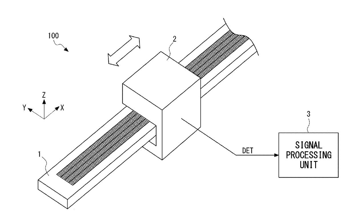
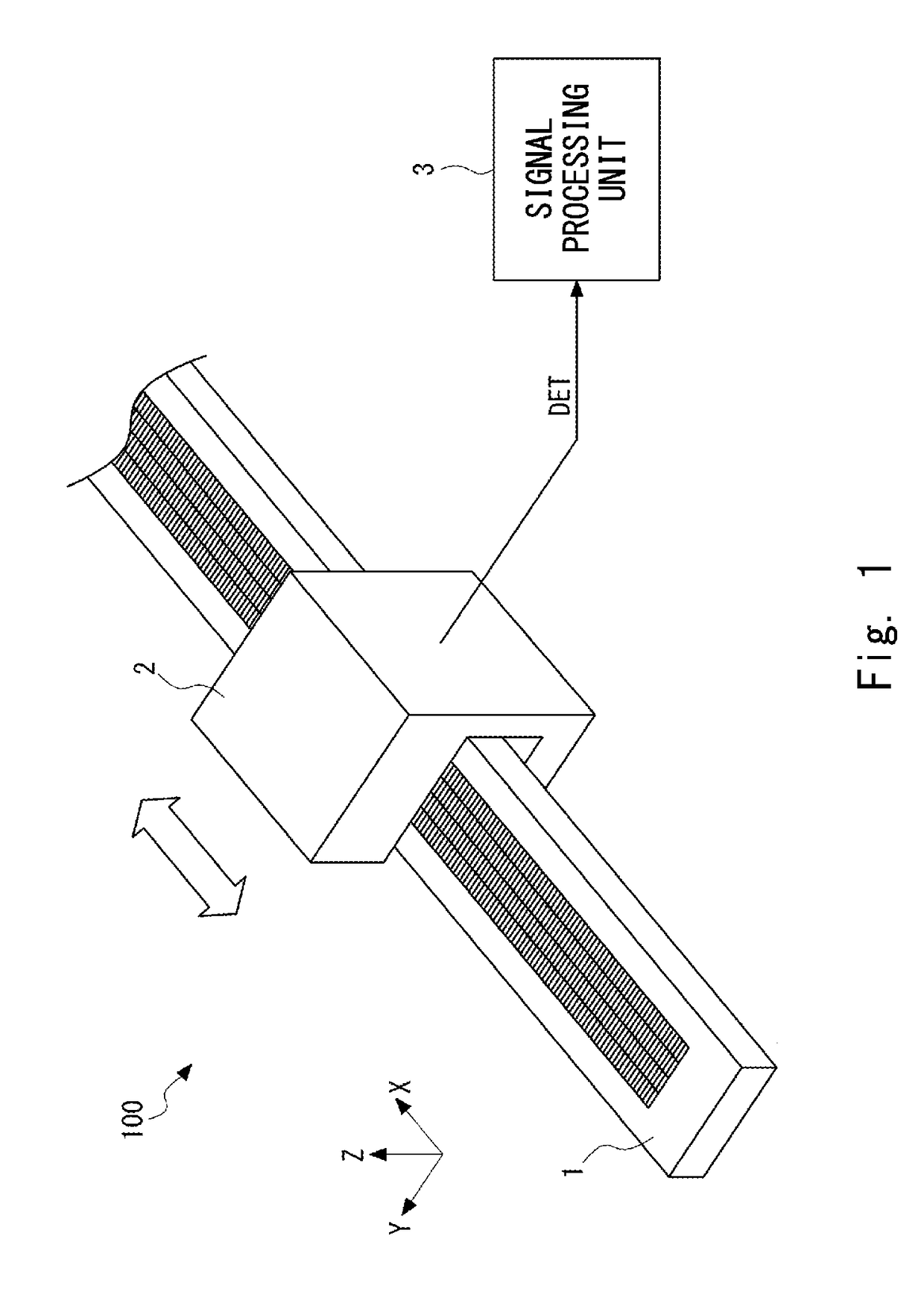
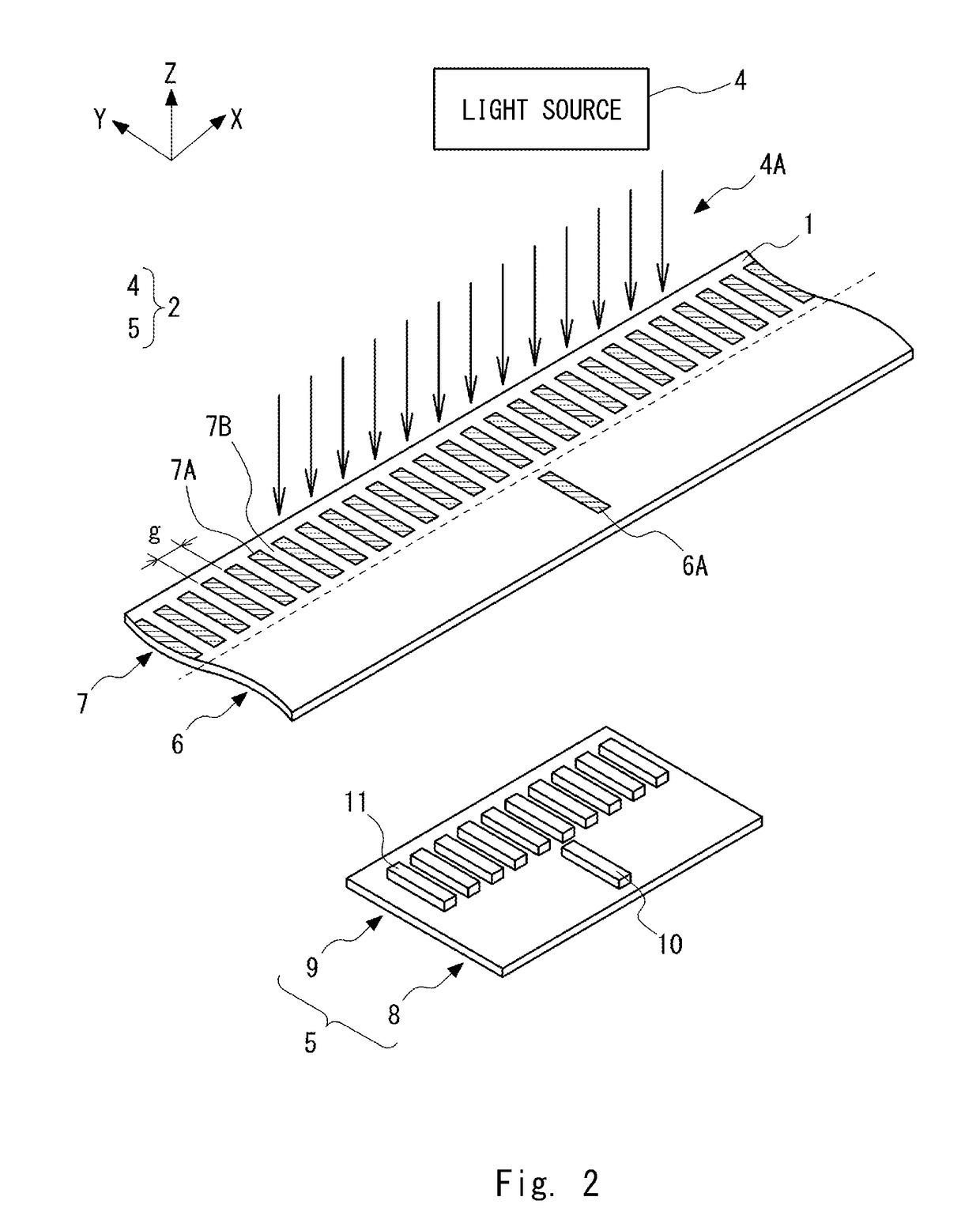
[0089]An optical displacement encoder according to a first exemplary embodiment of the present invention is explained. FIG. 1 is a perspective view showing a general configuration of an optical displacement encoder 100 according to the first exemplary embodiment. An example case where the optical displacement encoder 100 is constructed as a transmission-type displacement encoder is explained hereinafter. As shown in FIG. 1, the optical displacement encoder 100 includes a scale 1, a detection head 2, and a signal processing unit 3. The scale 1 and the detection head 2 are configured so that they can be moved relative to each other along a measurement direction (an X-axis direction in FIG. 1) which is in parallel with the longitudinal direction of the scale 1. A pattern used for position detection is formed in the scale 1. When light is applied (i.e., emitted) to the pattern, interference light is generated. The detection head 2 detects a change in the interference light in the measur...
example 1
[0109]FIG. 5 shows a relation between interference fringes and light-receiving elements according to Example 1. In Example 1, the number of arranged light-receiving elements is ten and the period (i.e., the cycle) with which the light-receiving elements are arranged (hereinafter referred to as an “arrangement period”) is equal to the fundamental period P of the interference fringes. Further, the width W of each of the light-receiving elements is 0.5 times the fundamental period P (i.e., a half of the fundamental period P) of the interference fringes. Note that in this example, light-receiving elements 11A and light-receiving elements 11B are alternately arranged.
[0110]As for the light-receiving elements 11A, they are arranged with a period 2P, i.e., twice the fundamental period P as shown in FIG. 5. As for the light-receiving elements 11B, they are also arranged with the period 2P, i.e., twice the fundamental period P. That is, the light-receiving elements 11A detect an optical inte...
example 2
[0113]FIG. 6 shows a relation between interference fringes and light-receiving elements according to Example 2. In Example 2, the number of arranged light-receiving elements is four and the arrangement period of the light-receiving elements is three times the fundamental period P of the interference fringes. Further, the width W of each of the light-receiving elements is 0.5 times the fundamental period P of the interference fringes. In this example, light-receiving elements 11A and light-receiving elements 11B are alternately arranged.
[0114]As for the light-receiving elements 11A, they are arranged with a period 6P, i.e., six times the fundamental period P as shown in FIG. 6. As for the light-receiving elements 11B, they are also arranged with a period 6P, i.e., six times the fundamental period P. That is, the light-receiving elements 11A detect an optical intensity at a phase θ in the interference fringes, which change with the period 2P, i.e., twice the fundamental period P. Mean...
PUM
 Abstract
Description
Claims
Application Information
 - R&D
- Intellectual Property
- Life Sciences
- Materials
- Tech Scout
- Unparalleled Data Quality
- Higher Quality Content
- 60% Fewer Hallucinations
Browse by: Latest US Patents, China's latest patents, Technical Efficacy Thesaurus, Application Domain, Technology Topic, Popular Technical Reports.
© 2025 PatSnap. All rights reserved.Legal|Privacy policy|Modern Slavery Act Transparency Statement|Sitemap|About US| Contact US: help@patsnap.com


