Engine device

a technology of engine and gearbox, which is applied in the direction of electrical control, marine propulsion, vessel construction, etc., can solve the problems of environmental protection, and achieve the effect of preventing the risk of getting lost and the like and being safe to sustain

Active Publication Date: 2018-10-18
YANMAR POWER TECHNOLOGY CO LTD
View PDF0 Cites 7 Cited by
  • Summary
  • Abstract
  • Description
  • Claims
  • Application Information

AI Technical Summary

Benefits of technology

[0023]In the aspect of the present invention, a combustion control is executed based on an estimated output signal, so that an emergency stop of the engine device at a time of output-loss can be prevented. Therefore, in cases of an engine device for a ship for example, since an output from the engine device can be ensured even in an emergency of losing an output signal, propulsion means for sustaining navigation of the ship can be ensured, and a risk of getting lost and the like can be prevented.
[0024]Further, with the aspect of the present invention, the engine device whose output has been lost can be operated temporarily until a transition to the operation of the auxiliary engine. Therefore, even when the engine device is in the output-lost state, the ship or the generator having the engine device will not be stopped. Therefore, even when the output signal of the engine device is lost, an emergency stop can be avoided and transition to the operation of the auxiliary engine device can be reliably made. Therefore, navigation of the ship having such an engine device or output of the generator having the engine device can be safely sustained.

Problems solved by technology

However, the exhaust gas of the diesel engine contains a large amount of nitrogen oxides, sulfur oxides, particulate matter, and the like which are harmful substances hindering preservation of the environment.

Method used


Image

  • Engine device
  • Engine device
  • Engine device

Examples


first embodiment

[0055]First, an overview of the ship is described. As shown in FIG. 1 to FIG. 3, the ship 1 of the present embodiment includes: a ship hull 2, a cabin 3 (bridge) provided on the stern side of the ship hull 2, a funnel 4 (chimney) positioned behind the cabin 3, and a pair of propellers 5 and a rudder 6 provided on a lower back portion of the ship hull 2. In this case, a pair of skegs 8 are integrally formed on the ship bottom 7 on the stern side. On each of the skegs 8, a propeller shaft 9 for driving to rotate the propeller 5 is pivotally supported. The skegs 8 are symmetrically formed on the left and right, with respect to the ship hull center line CL (see FIG. 3) which divides the lateral width direction of the ship hull 2. That is, the first embodiment adopts a twin skeg as the stern shape of the ship hull 2.

[0056]On a bow side and a middle part of the ship hull 2, a hold 10 is provided. On the stern side of the ship hull 2, an engine room 11 is provided. In the engine room 11, a...

second embodiment

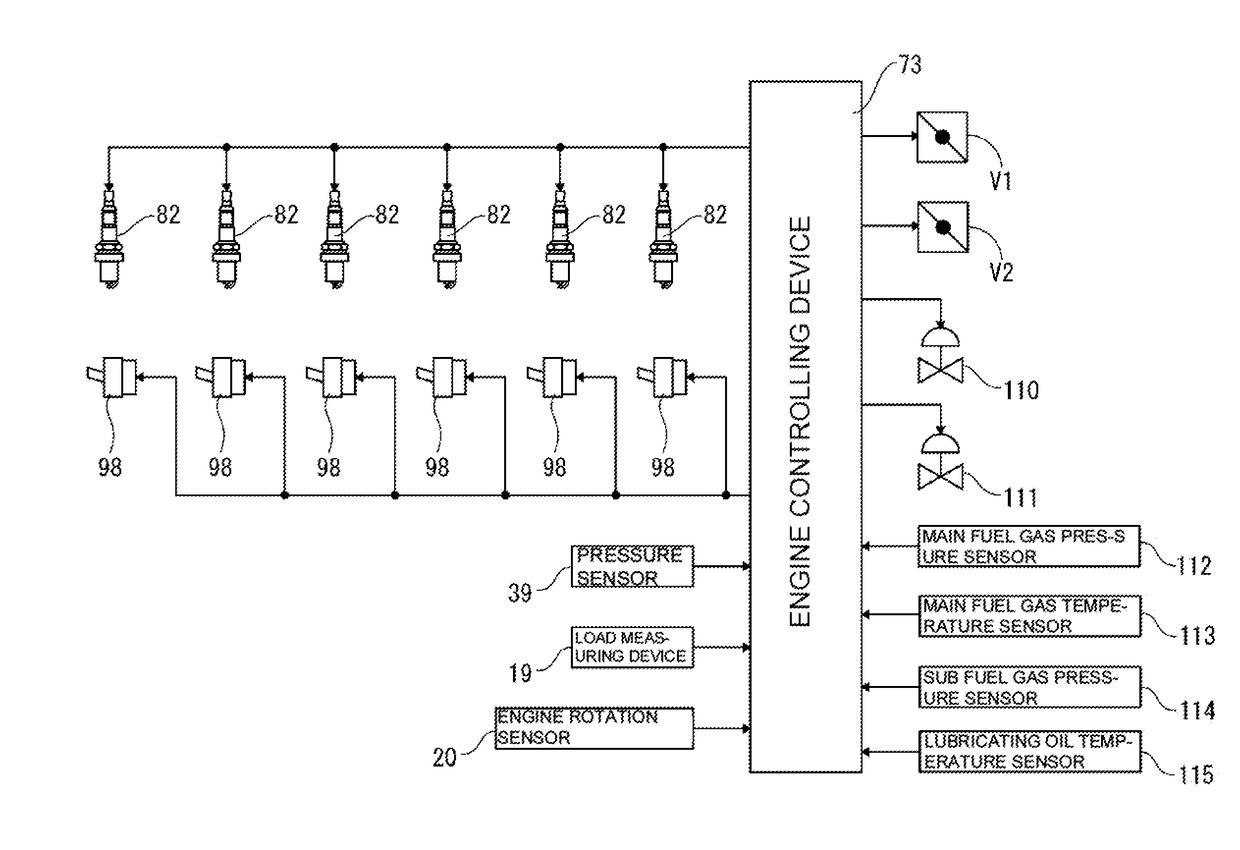
[0155]As shown in FIG. 25, in the gas mode operation of the engine device 21a of the second embodiment, the engine controlling device 73 sets the target ignition timing Dtm by referring to the target ignition timing map M4, and sets a retard amount ΔDTd by referring to a retardation setting map M5, to cause ignition by the pilot fuel injection valve 82a at an ignition timing DTm+ΔDTd. The target ignition timing map M4 indicates the correlation between the engine load (generator output or engine torque) Ac measured by the load measuring device 19 and the target ignition timing DTm, and is for determining the target ignition timing DTm with respect to the engine load Ac. The retardation setting map M5 indicates the correlation between a parameter based on which prediction of insufficiency in the air amount is based and the retard amount ΔDTd, and is for determining the retard amount ΔDTd with respect to the predicted air amount insufficient state.

[0156]As shown in FIG. 25, in the reta...


PUM


Abstract

An engine device including: an intake manifold (67) configured to supply air into a cylinder (77); a gas injector (98) configured to mix fuel gas with air supplied from the intake manifold (67), and supply mixed gas to the cylinder (77); an igniter (79) configured to ignite, in the cylinder (77), premixed fuel obtained by pre-mixing the fuel gas with the air; and a control unit (73) configured to execute a combustion control of a premixed fuel based on the output signal indicative of an output from the engine device. When the air amount is determined to be insufficient and when the output signal is lost, the control unit (73) estimates an output signal based on the fuel gas injection amount from the gas injector (98), and executes the combustion control based on the estimated output signal.

Description

TECHNICAL FIELD[0001]The present invention relates to an engine device to serve as a drive source, and particularly relates to an engine device configured to rotate an output shaft through combustion of a fuel gas.BACKGROUND ART[0002]Traditionally, diesel engines are used as a drive source of vessels such as tankers or transport ships and onshore power generation facilities. However, the exhaust gas of the diesel engine contains a large amount of nitrogen oxides, sulfur oxides, particulate matter, and the like which are harmful substances hindering preservation of the environment. For this reason, in recent years, gas engines that can reduce the amount of harmful substances generated are becoming prevalent as an alternative engine for diesel engines.[0003]A so-called gas engine that generates power by using a fuel gas such as natural gas supplies a mixed gas obtained by mixing a fuel gas with the air to a cylinder and combust the same (see Patent Literature 1 and Patent Literature 2...

Claims


Application Information

Patent Timeline
Patent Type & Authority Applications(United States)
IPC IPC(8): F02D41/22F02B69/04F02B43/04F02M21/04F02D41/00B63H21/21
CPCF02D41/222F02B69/04F02B43/04F02M21/04F02D41/0027B63H21/21B63H2021/216F02D19/025F02D19/10F02D25/00F02D29/06F02D41/0025F02D41/1401F02D2041/1433F02D2041/227F02D2200/1004F02B43/00F02M21/02Y02T10/30Y02T10/40F02B43/10F02D19/024F02D19/061F02D41/02F02D41/04F02D41/22
Inventor HAGIWARA, RYOICHIYAMAGISHI, OSAMUIKEDA, NAOYA
Owner YANMAR POWER TECHNOLOGY CO LTD
Why Eureka
Try Eureka