
A method and device for contraction monitoring

a technology of contraction monitoring and end device, which is applied in the field of pregnancy monitoring, can solve the problems of inability of a woman inability to provide a solution for contraction monitoring outside of controlled clinical settings, and inability to reliably identify a contraction. it can improve the experience and ease of use of contraction monitoring

Active Publication Date: 2018-10-18
BLOOM TECH NV
View PDF12 Cites 17 Cited by
  • Summary
  • Abstract
  • Description
  • Claims
  • Application Information

AI Technical Summary

Benefits of technology

The present invention is about a method for detecting motion artifacts in bio-potential signals, which can be used to estimate the uterine activity of a pregnant woman. The method combines electrohysterogram signals and inertial sensing module data to detect motion artifacts. The invention also provides feedback to the user based on the measured parameters and estimated information to improve lifestyle and reduce risks related to pregnancy. The sensor module is designed to be comfortable and easy to use, allowing the user to visualize all the signals and the information related to the uterus activity on a portable device and be accordingly informed. The technical effects of the invention include improved accuracy and reliability of uterine activity estimation, improved diagnosis of pregnancy-related risks, and improved user experience.

Problems solved by technology

The feeling of a contraction is completely new and it is impossible for a woman to reliably identify a contraction from other abdominal physiological disturbances such as abdominal cramps or bowel disturbances.
This is especially true for first time moms, but second and third time moms also report this problem, as they would often forget what a contraction feels like.
The answer to this question is inevitably inaccurate since a woman is not able to reliably report contractions.
Despite the importance of monitoring contractions outside the hospital or physician's office, from both a consumer and clinician perspective, there is to date no solution available for contraction monitoring outside controlled clinical settings.
Stopwatches rely on the woman's perception and feeling of a contraction, and are therefore intrinsically inaccurate and do not address the problem that woman cannot recognize or detect their contractions.
First, a tocograph is obtrusive, as it requires a woman to use a strap around her abdomen, a large pressure probe and gel.
The obtrusiveness of a tocograph limits its applicability outside controlled clinical environments.
As a consequence, the tocograph has to be operated by trained clinical staff and cannot be used by the pregnant woman herself.
Third, a tocograph only measures the result of the contraction (a change in pressure on the surface of the abdomen), and not the actual physiological phenomena leading to the contraction.
As a consequence, tocography have shown low accuracy in characterizing contractions, especially the intensity of the contractions.
However, such devices are today limited to bulky devices with electrodes and wires, operated by clinically experienced staff, and limited to the clinical environment.
However, such a concept of a disposable patch integrating all the electronics will inevitably be associated with a very high cost due to the cost of the electronic components, hindering is practicality and usability as a disposable system.
Furthermore, although a patch may be applicable for some pregnant women, attaching an adhesive on the abdomen of a pregnant women often will be considered uncomfortable as it may lead to itching sensations, irritations, allergies or other disturbances.
Furthermore, the devices of US2012 / 0150010-A1 and US2007 / 0255184-A1 are limited in their functionality.
These devices merely provide a measurement of the contraction signal, and do not perform any further analysis on the signal.
As a result they are of limited value to the user directly, but require the intervention of a clinically experienced staff to interpret the results.

Method used


Image

  • A method and device for contraction monitoring
  • A method and device for contraction monitoring
  • A method and device for contraction monitoring

Examples


Embodiment Construction

[0185]The present invention will be described with respect to particular embodiments and with reference to certain drawings but the invention is not limited thereto but only by the claims. The drawings described are only schematic and are non-limiting. In the drawings, the size of some of the elements may be exaggerated and not drawn on scale for illustrative purposes. The dimensions and the relative dimensions do not necessarily correspond to actual reductions to practice of the invention.

[0186]Furthermore, the terms first, second, third and the like in the description and in the claims, are used for distinguishing between similar elements and not necessarily for describing a sequential or chronological order. The terms are interchangeable under appropriate circumstances and the embodiments of the invention can operate in other sequences than described or illustrated herein.

[0187]Moreover, the terms top, bottom, over, under and the like in the description and the claims are used fo...


PUM


Abstract

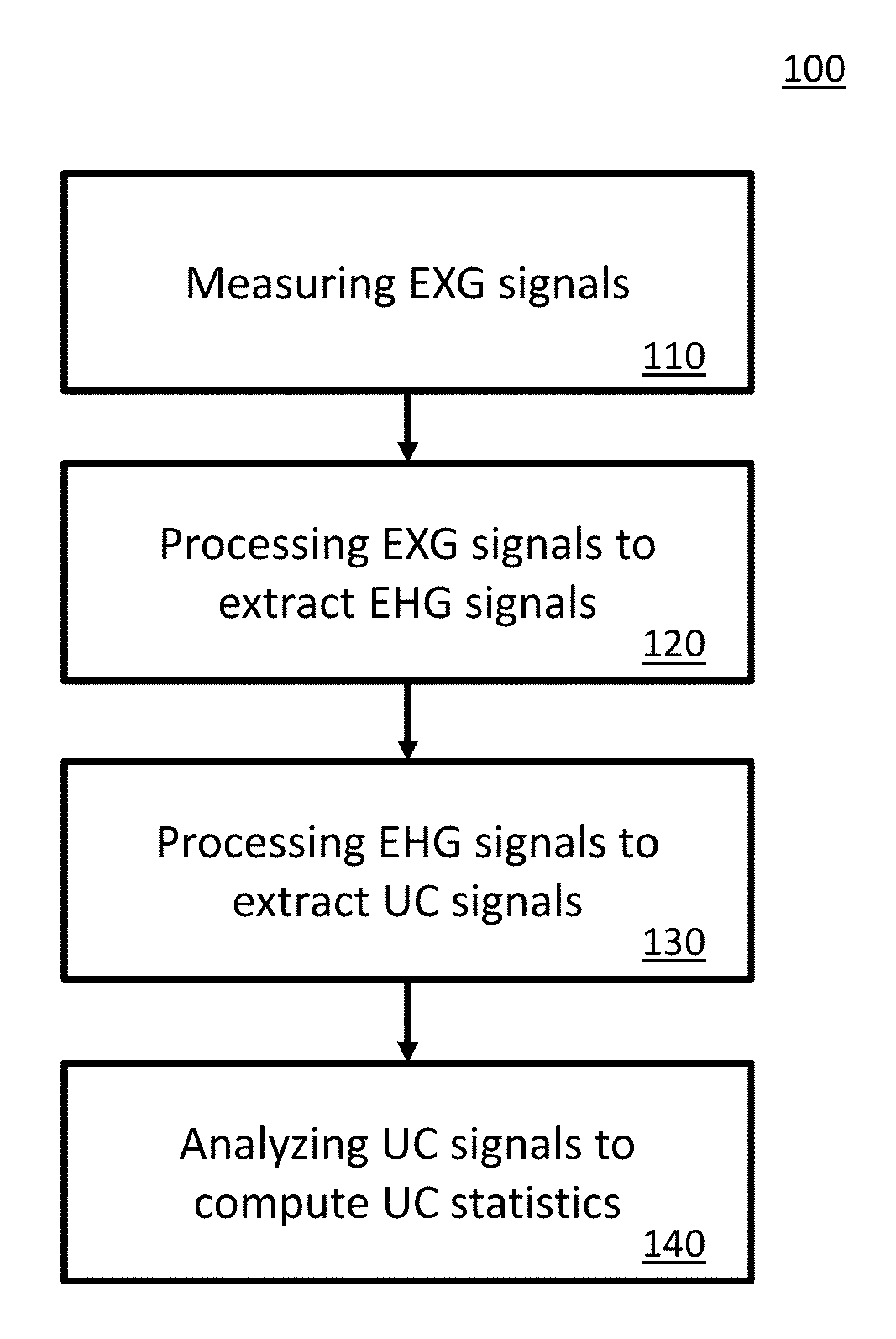
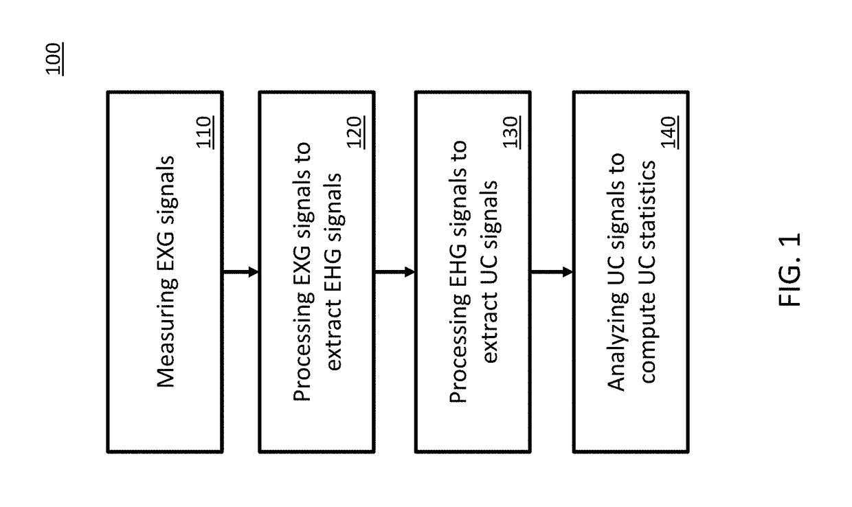
Described herein are systems and methods for contraction monitoring. For example, a system for contraction monitoring includes an electrode patch including at least two electrodes, and a sensor module configured to be connected to the electrode patch. In some embodiments, the sensor module includes a signal acquisition module, a signal processing module, a power management module, a sensor control module, and a memory module and / or a data transmission module. In some embodiments, a method for contraction monitoring includes measuring, using the signal acquisition module, bio-potential signals by providing at least two electrodes on the abdomen of a pregnant woman. In some embodiments, a method for contraction monitoring includes processing, using the signal processing module, the bio-potential signal to extract electrohysterogram signals, maternal electrocardiogram signals and fetus electrocardiogram signals, and processing using the signal processing module, the individual signals to extract uterine contraction.

Description

CROSS-REFERENCE TO RELATED APPLICATIONS[0001]This application claims priority benefits to U.S. provisional patent application Ser. No. 62 / 072,348, titled “Method and Device for Contraction Monitoring”, filed on Oct. 29, 2014, which is herein incorporated by reference in its entirety.[0002]This application claims foreign priority benefits to Belgium patent application No. BE2015 / 5056, titled “Method and Apparatus for Monitoring Contractions in Pregnancy” filed on Feb. 5, 2015, which, is herein incorporated by reference in its entirety.FIELD[0003]This invention relates to the field of pregnancy monitoring and more particularly to a method end device for contraction monitoring.[0004]Pregnant women are full of questions about their pregnancy, their bodies, and their babies. One of the most stressful questions for late term women is am I having contractions? Answering this question is key to understand when labor is starting, allowing a pregnant couple to prepare for the imminent deliver...

Claims


Application Information

Patent Timeline
Patent Type & Authority Applications(United States)
IPC IPC(8): A61B5/00A61B5/0448A61B5/16A61B5/024A61B5/288A61B5/344
CPCA61B5/4356A61B5/0448A61B5/165A61B5/02411A61B5/4362A61B5/721A61B5/1118A61B2503/02A61B5/6833A61B5/316A61B5/344A61B5/333A61B5/288A61B5/389A61B5/1107
Inventor PENDERS, JULIENALTINI, MARCODY, ERICBERSET, TORFINNROOIJAKKERS, MICHIEL
Owner BLOOM TECH NV
Learn More