Driving system for driving at least one auger of a snow removal device, a snow removal device provided with such a driving system, a kit for the installation of such a driving system, a method for installing such a driving system and a method for the manufacture of components or parts of the driving system

a driving system and driving system technology, applied in the direction of cleaning, construction, gearing, etc., can solve the problems of reducing maintenance steps, difficult to obtain existing snow removal devices, and adjusting the tension of roller chains

Active Publication Date: 2018-09-27
LES MACHINERIES PRONOVOST
View PDF15 Cites 2 Cited by
  • Summary
  • Abstract
  • Description
  • Claims
  • Application Information

AI Technical Summary

Benefits of technology

The patent text describes a snow removing device that has two parts: a front guard and a rear guard. The front guard is attached to the vehicle's lateral wall and prevents snow or debris from hitting the front part of the device. The rear guard is attached to the frame or the auger housing and prevents snow or debris from getting to the rear part of the device. This technology ensures that the device is protected and can effectively remove snow from the vehicle without getting damaged.

Problems solved by technology

However, these requirements are difficult to obtain with existing snow removal devices, especially snow blowers.
One of the biggest problem to be solved by the man skilled in the art is the adjustment of the tension of the roller chain 19.
However by limiting this elongation, the maintenance steps are reduced and the useful life of the roller chain, output gear and driving gear is increased.
Also, when the tensioning of the roller chain is too high, the noise generated by the movement of the roller chain on the output gear and the driving gear, increases to thereby cause an irritant to the snow blower operator and nearby residents during snow removal operations.
However, this simple system because of its fixed mounting, has the inconvenient that its adjustment must be made with tools.
Also, this simple system does not continuously apply a tension on the roller chain.
The inconvenient is that the spring 22 applies an additional force on the roller chain.
This additional force varies depending the compression of the spring, and this contributes to the elongation of the roller chain and / or generates additional noise, especially when the spring 22 is at its maximal adjustment position.
Also, this system comprises several mobile parts that can be worn and consequently necessitate additional lubrication.
This high number of mobile parts is hard to be perfectly aligned along the path of the roller chain, and consequently may further generates an additional risk of component damages.
However, it has never been used in a driving system for driving at least one auger of a snow removal device (such as a snow blower) for various reasons.
However, this system is fragile and subjected to derailing when used in an environment containing contaminants.

Method used


Image

  • Driving system for driving at least one auger of a snow removal device, a snow removal device provided with such a driving system, a kit for the installation of such a driving system, a method for installing such a driving system and a method for the manufacture of components or parts of the driving system
  • Driving system for driving at least one auger of a snow removal device, a snow removal device provided with such a driving system, a kit for the installation of such a driving system, a method for installing such a driving system and a method for the manufacture of components or parts of the driving system
  • Driving system for driving at least one auger of a snow removal device, a snow removal device provided with such a driving system, a kit for the installation of such a driving system, a method for installing such a driving system and a method for the manufacture of components or parts of the driving system

Examples


Embodiment Construction

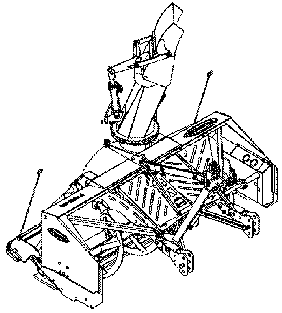
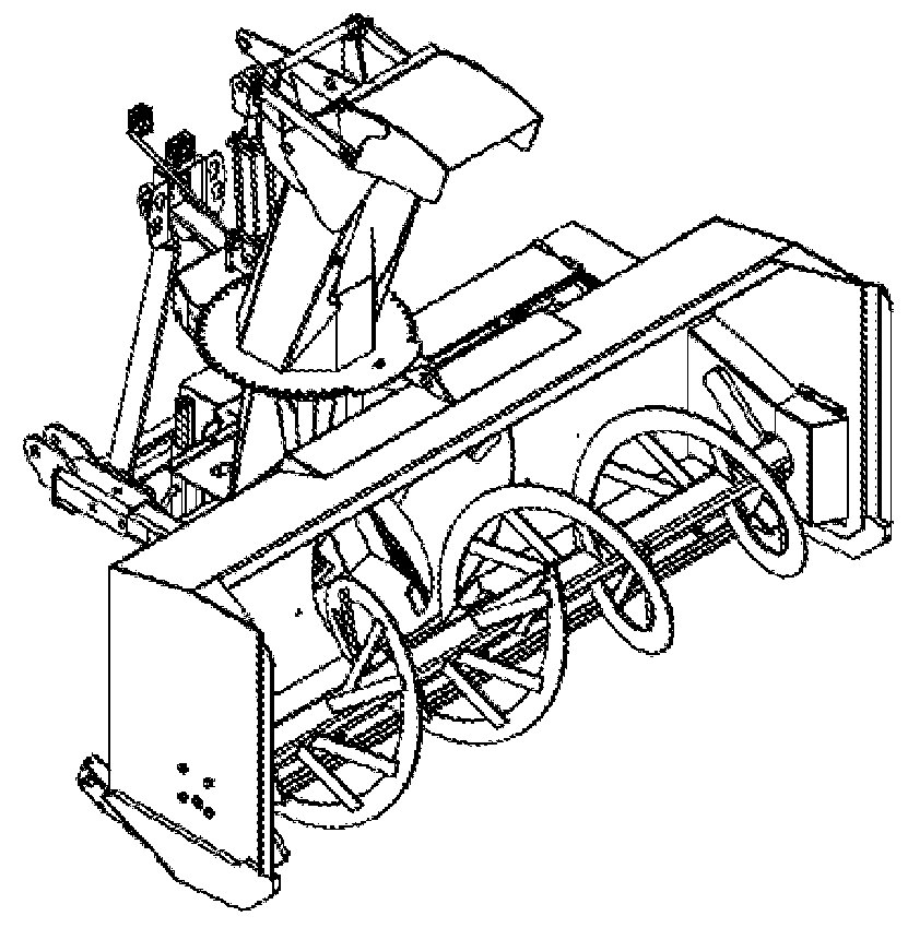
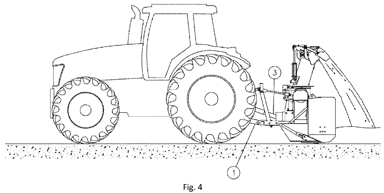
[0133]Various embodiments are described in the following disclosure with reference to the accompanying figures. It should be understood that elements of these figures are not necessarily depicted to scale, since emphasis is placed upon clearly illustrating the elements and structures of the present embodiments.

[0134]In the following description, same numerical references refer to similar elements. Furthermore, for the sake of simplicity and clarity, namely so as to not unduly burden the figures with several reference numbers, not all figures contain references to all the components and features, and references to some components and features may be found in only one figure, and components and features of the present disclosure which are illustrated in other figures can be easily inferred therefrom. The embodiments, geometrical configurations, materials mentioned and / or dimensions shown in the figures are optional, and are given for exemplification purposes only.

[0135]Also, as will b...


PUM


Abstract

A driving system for driving at least one auger of a snow removing device comprising at least one at least one self-adjusting chain tensioner. A first portion of the driving system is positioned within an auger housing and a second portion of the driving system is positioned outside the auger housing. The roller chain is adapted to move across a third opening provided in the auger housing. The first portion is covered by a front guard to prevent snow or debris contained in the auger housing to contact said first portion. The front guard is provided with an opening adapted to surround a portion of a shaft element of the auger with a play between periphery of the opening and the periphery of a corresponding portion the shaft element. The play is either small enough to prevent water and or debris to enter the first casing, or filled with a filling element and / or covered with a sealing element secured to the front guard or the corresponding portion of the shaft element of the at least one auger, to have the play small enough to prevent water and / or debris to enter the first casing. The second portion prevent snow or debris present around the snow removing device to contact the said second portion. A snow blower provided with the driving system, a kit comprising parts and / or components of the driving system, a method for assembling the driving system, and a method for manufacturing some components or parts of the driving system.

Description

CROSS REFERENCE TO A RELATED APPLICATION[0001]The present patent application claims the priority of Canadian patent application no. 2 961 915 filed on Mar. 24, 2017, the content of which is incorporated herein in its entirety.FIELD OF THE INVENTION[0002]The present invention relates to the field of snow removal devices. More particularly, the present invention relates to a new driving system for driving at least one auger of a snow removal devices, and also relates to a snow removal device provided with such a driving system. Also, the invention relates to a kit and a method for the installation of the new driving system on a snow removal device. Also, the invention relates to a method for the manufacture of components and / or parts of the driving system. Preferably, the snow removal devices may be a snow thrower or a snow blower, preferably a snow blower.BACKGROUND[0003]Snow blowers are well known in the art. They may be intended for domestic, commercial or industrial uses (see FIG....

Claims


Application Information

Patent Timeline
Patent Type & Authority Applications(United States)
IPC IPC(8): E01H5/07E01H5/04F16H7/12F16H7/14
CPCE01H5/076E01H5/045F16H7/1209F16H7/14F16H2007/0844
Inventor CHAMPAGNE, CHRISTIANBELLEVILLE, BENOÎTBEAULIEU, NORMANDPRONOVOST, RÉJEAN
Owner LES MACHINERIES PRONOVOST
Why Eureka
Try Eureka