Ultrapolar electrosurgery blade and ultrapolar electrosurgery blade assembly with conductive contacts on top, bottom, sides and cutting edge of blade

Active Publication Date: 2018-09-20
IC MEDICAL
View PDF7 Cites 2 Cited by
  • Summary
  • Abstract
  • Description
  • Claims
  • Application Information

AI Technical Summary

Benefits of technology

The present invention provides an ultrapolar electrosurgery blade that uses a single thin conductive member with vertically aligned conductive members separated by a sharp non-conductive cutting edge. This blade design facilitates the construction and production of the blade with consistency and accuracy, and increases the strength of the blade. The blade can be used for both cutting and coagulation simultaneously, and can also enhance the cutting of tissue using RF energy. The ultrapolar electrosurgery blade is advantageous in reducing damage to the patient's lateral tissue, and can also perform non-contact argon beam coagulation. The ultrapolar electrosurgery blade assembly with argon beam capability is capable of coagulating a patient's tissue using argon plasma alone without contacting the patient's tissue, and can also enhance the cutting of tissue using the sharp conductive cutting edges of the blade.

Problems solved by technology

However, the high power necessary to conduct monopolar electrosurgery and the excessive heat generated with monopolar electrosurgery can cause excessive tissue damage and necrosis of the tissue because the return electrode positioned on the back of the patient causes high voltage and high RF energy to pass through the patient.
Although bipolar electrosurgery enables the use of lower voltages and less energy and thereby reduces or eliminates the likelihood of tissue damage and sparking associated with monopolar electrosurgery, it has limited ability to cut and coagulate large bleeding areas.

Method used


Image

  • Ultrapolar electrosurgery blade and ultrapolar electrosurgery blade assembly with conductive contacts on top, bottom, sides and cutting edge of blade
  • Ultrapolar electrosurgery blade and ultrapolar electrosurgery blade assembly with conductive contacts on top, bottom, sides and cutting edge of blade
  • Ultrapolar electrosurgery blade and ultrapolar electrosurgery blade assembly with conductive contacts on top, bottom, sides and cutting edge of blade

Examples


Embodiment Construction

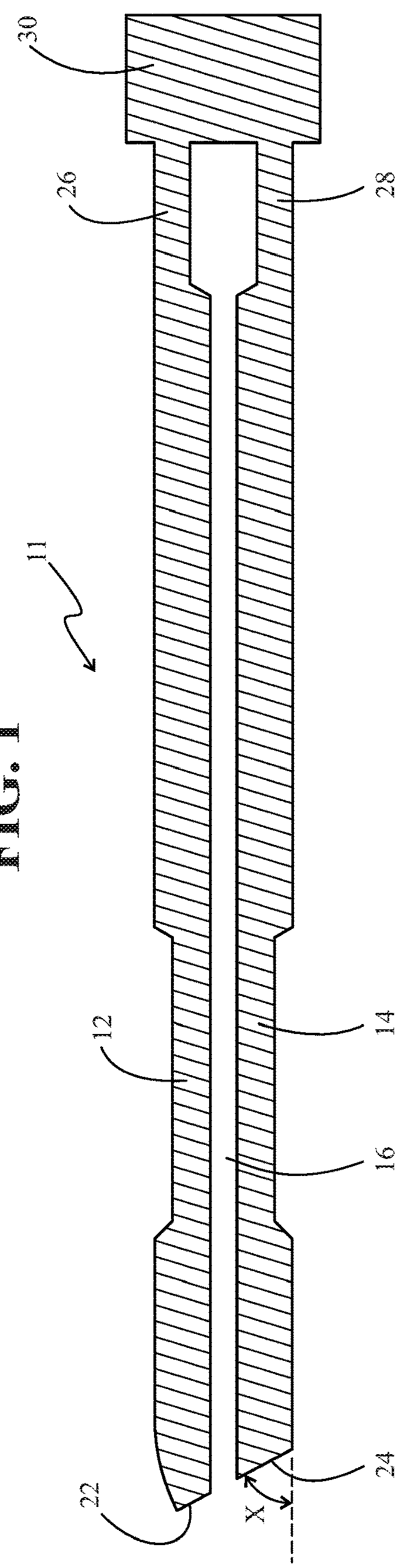
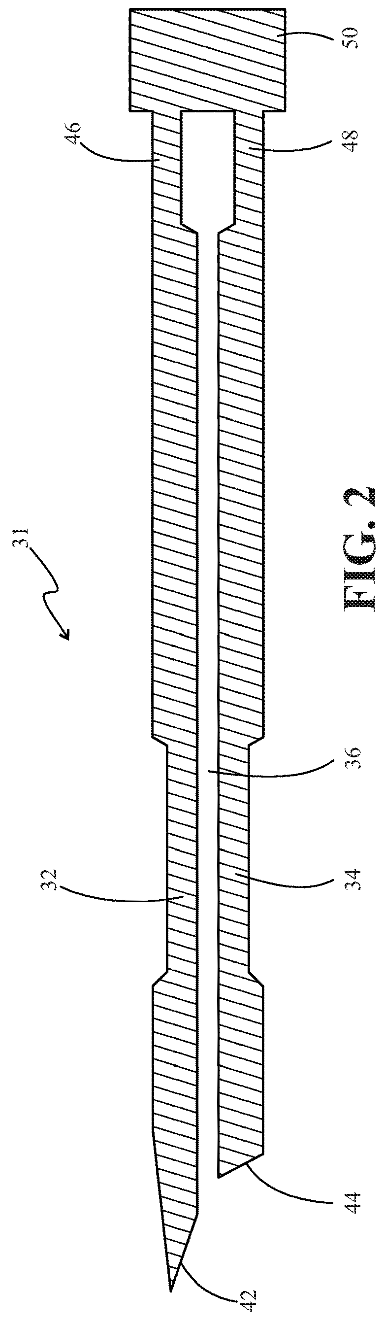
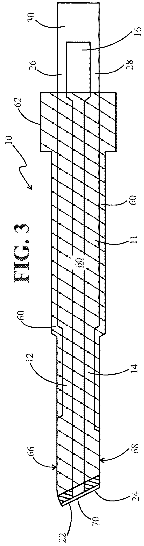
[0045]The exemplary embodiments of the ultrapolar electrosurgery blade and ultrapolar electrosurgery blade assembly having argon beam capability of the present invention enable the surgeon or user to increase both the efficiency and accuracy of the surgery by enabling the surgeon or user to perform different methods of cutting and coagulating tissue either separately or simultaneously. The ultrapolar electrosurgery blade of the present invention is capable of cutting tissue with the sharp conductive cutting ends of the blade without using RF energy as well as cutting tissue with the sharp non-conductive cutting end / edge that is located between the sharp conductive cutting ends. In addition, the ultrapolar electrosurgery blade of the present invention is capable of coagulating tissue and / or enhanced cutting of tissue by supplying very low power, such as 5 to 15 watts, to the ultrapolar electrosurgery blade, and simultaneously cutting and coagulating tissue by cutting tissue with the ...


PUM


Abstract

An ultrapolar electrosurgery blade includes lop and bottom thin elongated conductive members in vertical, alignment and spaced apart, from one another along their lengths, a non-conductive coating covering both the top and bottom thin elongated conductive members and the space located between them to create opposing non-conductive sides of the blade with conductive cutting and ends and conductive non-cutting ends exposed, and both return and active contact layers located on each of the opposing non-conductive sides of the blade. An ultrapolar electrosurgery blade assembly having argon beam capability further includes a non-conductive tube member having a slot positioned over the top of the ultrapolar electrosurgery blade and a conductive hollow tubular member contained within at least a portion of the non-conductive tube member.

Description

CROSS-REFERENCE TO RELATED APPLICATIONS[0001]This application relates to provisional patent applications having Ser. Nos. 62 / 467,739and 62 / 576,213 and their related utility application having Ser. No. 15 / 913,569, filed on Mar. 6, 2018. Further, this application claims priority is to provisional patent application having Ser. No. 62 / 470,400, filed Mar. 13, 2017, and provisional patent application having Ser. No. 62 / 576,222, filed Oct. 24, 2017, which are all herein incorporated by reference in their entireties.FIELD OF INVENTION[0002]The present invention is generally directed to an ultrapolar electrosurgery blade and an ultrapolar electrosurgery blade assembly which uses monopolar energy in a bipolar mode for cutting and coagulation. The ultrapolar electrosurgery blade is the same as that disclosed in provisional applications having Ser. No. 62 / 467,739 and Ser. No. 62 / 576,213 and their related utility patent application having Ser. No. 15 / 913,569 [which includes top and bottom thin ...

Claims


Application Information

Patent Timeline
IPC IPC(8): A61B18/04A61B18/16A61B18/14
CPCA61B18/04A61B18/16A61B18/1477A61B2018/1412A61B2018/00083A61B2018/00077A61B2018/00607A61B2218/008A61B2018/162A61B2018/126A61B2018/00583A61B18/042A61B2018/1467
Inventor COSMESCU, IOAN
Owner IC MEDICAL
Why Eureka
Try Eureka