Suction filter and fuel supply device

Inactive Publication Date: 2018-09-13
DENSO CORP
View PDF4 Cites 4 Cited by
  • Summary
  • Abstract
  • Description
  • Claims
  • Application Information

AI Technical Summary

Benefits of technology

The present patent text is about a new suction filter for a fuel tank that aims to stabilize the performance of a fuel pump. The filter has a unique design that prevents fuel from leaking out when the vehicle is turned or the fuel level is low. This is achieved by forming a liquid film on the filter element, which prevents air from entering the inlet port. This helps to stabilize the fuel pump and ensures a steady supply of fuel to the engine.

Problems solved by technology

Hence, fuel in the space between the filter element and the storing member readily leaks out from the inflow hole when the liquid surface tilts during turning motion or the like of the vehicle.
Accordingly, an amount of trapped fuel in the space between the filter element and the storing member is reduced and an amount of the trapped fuel becomes insufficient in a short time while fuel is drawn into the inlet port.

Method used


Image

  • Suction filter and fuel supply device
  • Suction filter and fuel supply device
  • Suction filter and fuel supply device

Examples


first embodiment

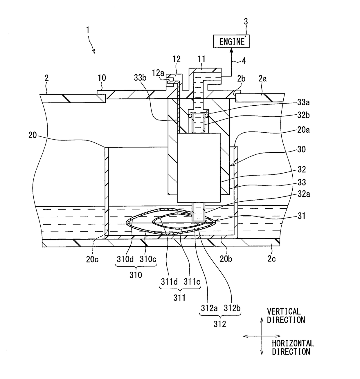
[0038]As is shown in FIG. 1, a fuel supply device 1 according to a first embodiment of the present disclosure is installed to a fuel tank 2 of a vehicle. The fuel supply device 1 supplies fuel inside the fuel tank 2 to an internal combustion engine 3 outside the fuel tank 2. The fuel tank 2 equipped with the fuel supply device 1 is made of resin and formed in a hollow shape to store fuel to be supplied to a side of the internal combustion engine 3. The internal combustion engine 3 supplied with fuel from the fuel supply device 1 may be a gasoline engine or a diesel engine. A horizontal direction and a vertical direction in the vehicle on a level surface substantially coincides, respectively, with a horizontal direction and a vertical direction specified in FIG. 1.

[0039]An overall configuration of the fuel supply device 1 will be described first.

[0040]The fuel supply device 1 includes a flange 10, a sub-tank 20, and a pump unit 30.

[0041]The flange 10 is made of hard resin and formed ...

second embodiment

[0061]As are shown in FIGS. 4 and 5, a second embodiment of the present disclosure is a modification of the first embodiment above. A partition wall element 2311 of the second embodiment is formed in a hollow cylindrical shape in the inner space 312 of the filter element 310 with an outer surface 2311a being exposed to the first space 312a and an inner surface 2311b completely enclosing the second space 312b. In particular, the partition wall element 2311 is formed by liquid-tightly bonding a pair of partition wall members 2311c and 2311d in such a manner that a rectangular cylindrical shape is formed by connecting an upper wall 2311f and a lower wall 2311g substantially parallel to bottoms 2c and 20b of the tanks 2 and 20, respectively, with four walls. Owing to such a configuration, the partition wall element 2311 completely divides the inner space 312 of the filter element 310 to the first space 312a and the second space 312b in the sub-tank 20 inside the fuel tank 2. When the re...

third embodiment

[0068]As is shown in FIG. 7, a third embodiment of the present disclosure is another modification of the first embodiment above. A partition wall element 3311 of the third embodiment is provided in a form of a partition film which completely divides the inner space 312 of the filter element 310 to an upper first space 3312a and a lower second space 3312b in the sub-tank 20 inside the fuel tank 2. In particular, the partition wall element 3311 is bonded between filter sheets 310c and 310d all along respective outer peripheral edges and therefore stretched across the inner space 312 in a form of a flat film. Owing to such a bonding configuration, the first space 3312a is enclosed by the partition wall element 3311 and the upper filter sheet 310d, and an upper surface 3311a of the partition wall element 3311 is thus exposed to the first space 3312a. Also, the second space 3312b is enclosed by the partition wall element 3311 and the lower filter sheet 310c and a lower surface 3311b of t...


PUM

PropertyMeasurementUnit
Volumeaaaaaaaaaa
Flexibilityaaaaaaaaaa
Surface roughnessaaaaaaaaaa

Abstract

A suction filter which filters fuel inside a fuel tank of a vehicle to let a fuel pump draw filtered fuel into an inlet port includes a filter element disposed inside the fuel tank and filtering stored fuel stored in the fuel tank by allowing the stored fuel to pass through to an inner space, and a partition wall element disposed in a posture with which to divide the inner space to a first space where filtered fuel filtered at the filter element flows in and a second space where the inlet port into which the filtered fuel is drawn opens, and allowing the filtered fuel in the first space to pass through to the second space. The partition wall element is provided in a form of a partition film dividing the inner space to the first space on an upper side and the second space on a lower side.

Description

CROSS REFERENCE TO RELATED APPLICATION[0001]This application is based on Japanese Patent Application No. 2015-6179 filed on Jan. 15, 2015, Japanese Patent Application No. 2015-142169 filed on Jul. 16, 2015, and Japanese Patent Application No. 2015-240567 filed on Dec. 9, 2015, the disclosures of which are incorporated herein by reference.TECHNICAL FIELD[0002]The present disclosure relates to a suction filter and a fuel supply device provided with a suction filter.BACKGROUND ART[0003]A fuel supply device in the related art supplying fuel from inside a fuel tank to outside the fuel tank in a vehicle includes a fuel pump disposed inside the fuel tank. The fuel pump draws fuel into an inlet port and discharges the drawn fuel outside the fuel tank. A device disclosed in Patent Literature 1 as an example of the fuel supply device in the related art is provided with a suction filter for the fuel pump to draw fuel into the inlet port after fuel is filtered inside the fuel tank.[0004]The suc...

Claims


Application Information

Patent Timeline
IPC IPC(8): B01D29/11B01D35/02F02M37/22B01D29/00F02M37/34F02M37/44F02M37/50
CPCB01D29/114B01D35/02F02M37/22B01D29/0054F02M2037/228F02M37/10B01D2201/60B01D2201/32B01D35/0273F02M37/50F02M37/44F02M37/34B01D29/54B01D29/58
Inventor HAYASHI, NORIHIROOIKAWA, SHINOBUNAGATA, KIYOSHIOKAZONO, TETSURO
Owner DENSO CORP
Why Eureka
Try Eureka