
Holographic detection and characterization of large impurity particles in precision slurries

a technology of impurity particles and characterization, which is applied in the direction of material analysis, phase-affecting property measurements, instruments, etc., can solve the problems of affecting the aggregation and elimination of contaminants, and affecting the quality of slurries

Active Publication Date: 2018-09-06
NEW YORK UNIV
View PDF1 Cites 3 Cited by
  • Summary
  • Abstract
  • Description
  • Claims
  • Application Information

AI Technical Summary

Benefits of technology

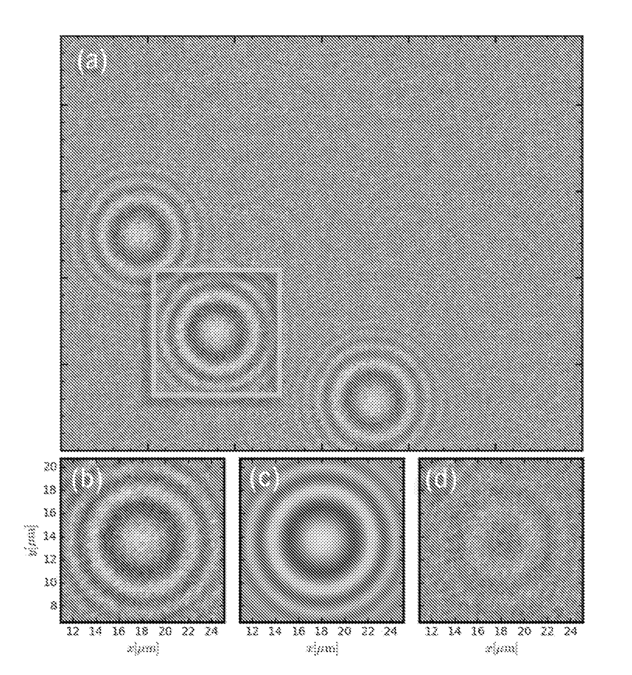
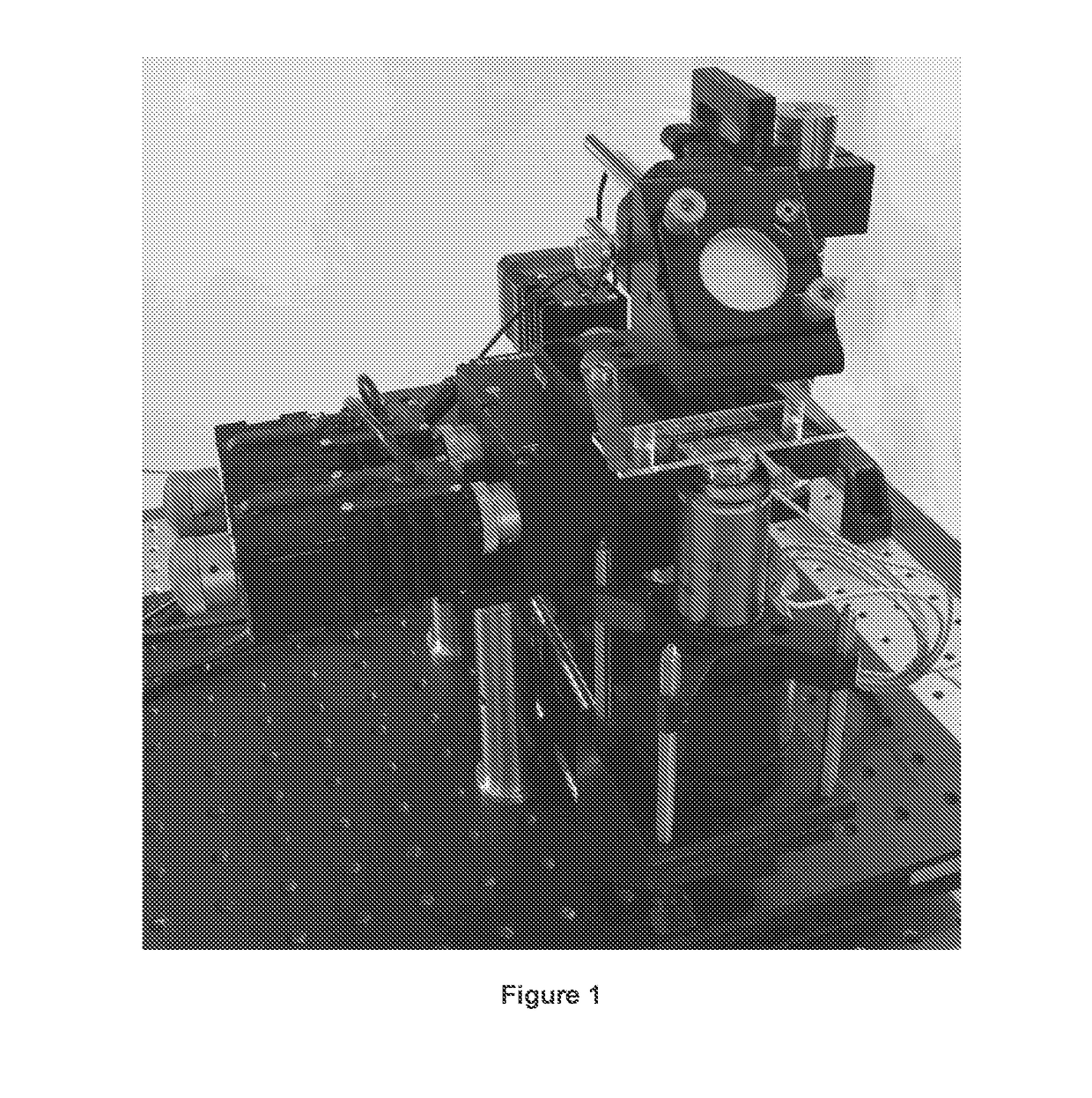
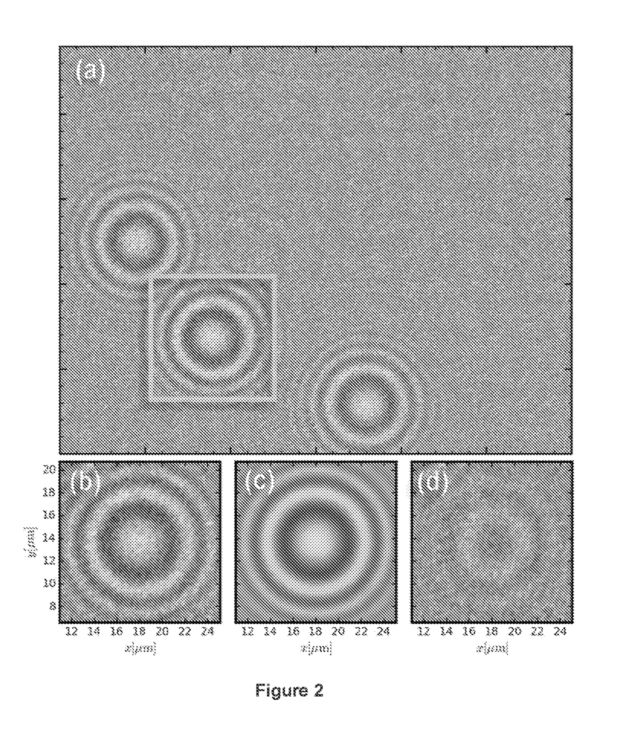
The patent describes a method for characterizing impurities in a sample using a holographic microscope. The method involves observing the sample and creating a hologram image of it. The image is then analyzed to identify specific particles of interest. The properties of these particles can be determined by fitting them to a theory of light scattering. This approach allows for the rapid and accurate identification of impurities in a sample, which can help in the manufacturing process of a product. Another embodiment of the method involves applying a special analysis to the hologram image and characterizing the particles of interest in a slurry sample. Overall, this patent provides a reliable and effective method for identifying and characterizing impurities in samples.

Problems solved by technology

The presence of aggregates or other oversize contaminants in CMP slurries is highly undesirable because of their adverse effect on surface quality, even at part-per-billion concentrations.
Efforts to prevent aggregation and eliminate contaminants are hampered by a lack of techniques for detecting and characterizing comparatively small numbers of large particles in an ocean of nanoparticles.
Conventional particle counters are clogged and fouled by slurry particles at full concentration.
Remedying these problems by dilution is impractical both because of the very large volume of fluid that then would have to be analyzed and also because the process of dilution can influence aggregation processes that might be of interest.

Method used


Image

  • Holographic detection and characterization of large impurity particles in precision slurries
  • Holographic detection and characterization of large impurity particles in precision slurries
  • Holographic detection and characterization of large impurity particles in precision slurries

Examples


Embodiment Construction

[0013]In the following detailed description, reference is made to the accompanying drawings, which form a part hereof. In the drawings, similar symbols typically identify similar components, unless context dictates otherwise. The illustrative embodiments described in the detailed description, drawings, and claims are not meant to be limiting. Other embodiments may be utilized, and other changes may be made, without departing from the spirit or scope of the subject matter presented here. It will be readily understood that the aspects of the present disclosure, as generally described herein, and illustrated in the figures, can be arranged, substituted, combined, and designed in a wide variety of different configurations, all of which are explicitly contemplated and made part of this disclosure.

[0014]Described herein are systems and methods of in-line holographic video microscopy. Embodiments of the in-line holographic video microscopy systems and methods addresses the need by identify...


PUM


Abstract

Impurities within a sample are detected by use of holographic video microscopy. The sample flows through the microscope and holographic images are generated. The holographic image is analyzed to identify regions associated with large impurities in the sample. The contribution of the particles of the sample to the holographic images is determined and the impurities are characterized.

Description

CROSS-REFERENCE TO RELATED APPLICATIONS[0001]This application is the U.S. national phase application under 35 U.S.C. § 371 of International Application No. PCT / US2016 / 051946 filed Sep. 15, 2016, which claims priority benefit of U.S. Provisional Application No. 62 / 220,786 filed Sep. 18, 2015, both incorporated herein by reference in their entirety.BACKGROUND OF THE INVENTION[0002]Slurries of oxide nanoparticles have widespread applications as polishing and lapping agents for photonics and for chemical mechanical planarization (CMP) of microelectronic devices. The presence of aggregates or other oversize contaminants in CMP slurries is highly undesirable because of their adverse effect on surface quality, even at part-per-billion concentrations. Efforts to prevent aggregation and eliminate contaminants are hampered by a lack of techniques for detecting and characterizing comparatively small numbers of large particles in an ocean of nanoparticles. Direct imaging, laser occultation and ...

Claims


Application Information

Patent Timeline
IPC IPC(8): G01N15/02G01N15/14G01N21/45G03H1/04G03H1/00
CPCG01N15/0227G01N15/1463G01N15/1459G01N21/453G03H1/0443G03H1/0005G01N2015/0053G01N2015/0233G01N2015/1454G01N2015/1493G03H2001/0033G03H2001/005G03H2001/0447G01N15/1434G01N15/1433
Inventor RUFFNER, DAVID B.GRIER, DAVID G.PHILIPS, LAURA
Owner NEW YORK UNIV
Learn More